Light aviation bearing rod piece and producing method thereof

A technology of load-bearing rods and load-bearing components, applied in the direction of slender elements, building elements, etc., can solve the problems of insufficient rigidity, heavy weight of components, high cost, etc., and achieve low transverse shear stress, super rigidity and Strength, the effect that the manufacturing method is simple

Inactive Publication Date: 2016-02-03
TONGJI UNIV
View PDF8 Cites 2 Cited by
  • Summary
  • Abstract
  • Description
  • Claims
  • Application Information

AI Technical Summary

Problems solved by technology

[0007] 1) The metal structure cannot be optimally designed for anisotropy, and the previous composite materials cannot take into account the characteristics of anisotropic carbon fiber composite materials, cannot make full use of the material properties, and the weight of the components themselves is too heavy;
[0008] 2) There are weak links in the connection between the metal and the carbon fiber composite material at the key bearing part, which affects the bearing capacity of the component;
[0009] 3) When the geometric size of the component is small, the stiffness involved often fails to meet the requirements due to the different weaving methods of the fibers;
[0010] 4) The manufacturing technology is targeted, and the cost is relatively high, so it is necessary to further optimize the design to reduce the manufacturing cost

Method used


Image

  • Light aviation bearing rod piece and producing method thereof
  • Light aviation bearing rod piece and producing method thereof
  • Light aviation bearing rod piece and producing method thereof

Examples


Embodiment

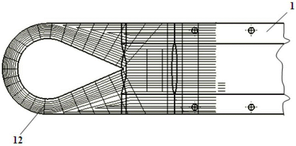
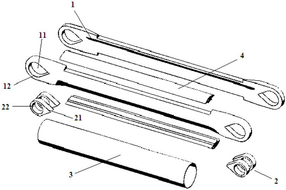
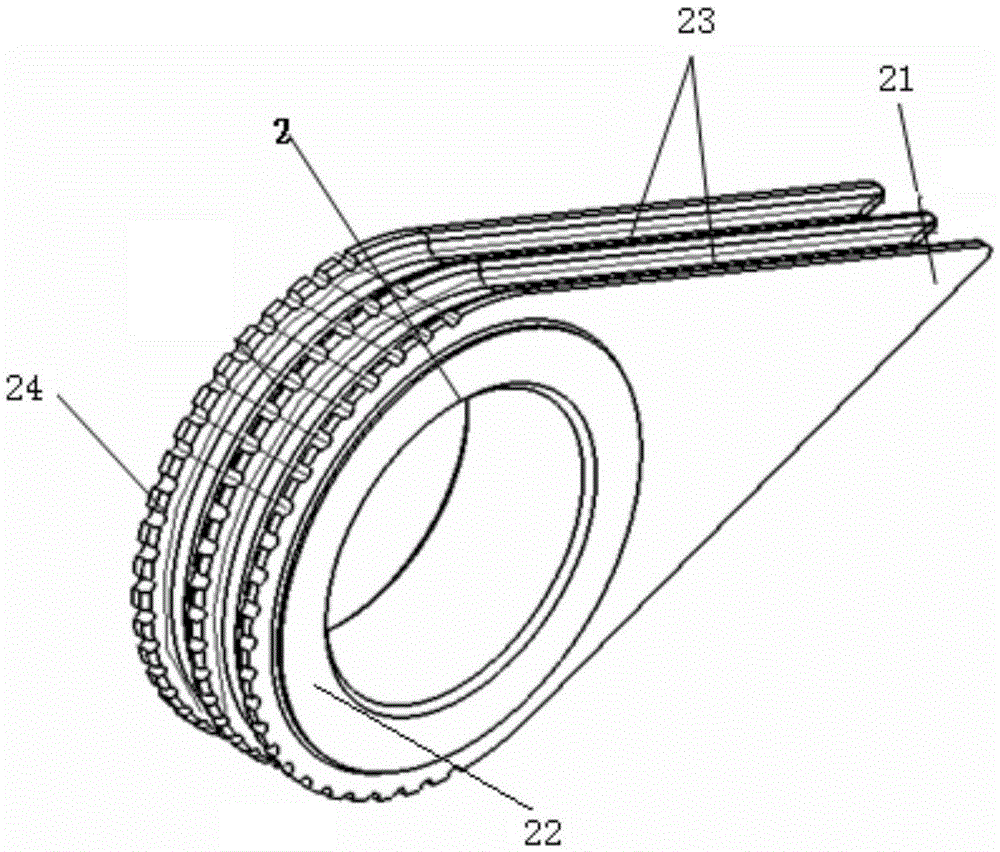
[0039] Such as Figure 1-2 As shown, an aviation light-weight load-bearing rod, including two load-bearing members 1, two inner liners 4, metal bushings 2 and tubular covering layers 3, the two sides of the load-bearing member 1 are respectively embedded in two oppositely arranged In the inner liner 4 of the inner liner 4, a circular tubular tie rod structure is formed, and the tubular covering layer 3 is wrapped on the outside of the load-bearing member 1 and the inner liner 4, and the two ends of the load-bearing member 1 are respectively provided with ear parts 12, and the ear parts 12 A drop-shaped through-hole 11 is provided on the top, and the metal bushing 2 is arranged in the through-hole 11. The outer surface of the metal bushing 2 is provided with a plurality of annular longitudinal grooves 23 longitudinally, and a plurality of ring-shaped longitudinal grooves 23 are arranged horizontally along the circumference of the circular through-hole. Transverse grooves 24 equ...


PUM


Abstract

The invention relates to a light aviation bearing rod piece. The light aviation bearing rod piece comprises two bearing members, two inner liners, a metal shaft sleeve and a tubular covering layer, wherein the two side surfaces of each bearing member are embedded into the two opposite inner liners respectively to form a round tubular pull rod structure; the bearing members and the inner liners are covered with the tubular covering layer; lug piece parts are arranged at the two ends of the bearing members respectively; drop-shaped through holes are formed in the lug piece parts; the metal shaft sleeve is arranged in the through holes; a plurality of annular longitudinal grooves are longitudinally formed in the outer surface of the metal shaft sleeve, and a plurality of transverse grooves which are distributed at equal intervals along the circumference of a round through hole are transversely designed. Compared with the prior art, the light aviation bearing rod piece has the advantages that the producing method is simple and convenient, the bearing capacity is high, and the like.

Description

technical field [0001] The invention relates to the technical field of lightweight composite materials, in particular to an aviation lightweight bearing bar and a manufacturing method thereof. Background technique [0002] For structural manufacturing technologies in the fields of aviation, aerospace, automobiles, rail transit vehicles, etc., the load-bearing structural parts can adapt to more severe environmental conditions, such as large temperature difference changes between low and high temperatures, vibration, fatigue, etc. , is an urgent need for the development of today's new technologies, especially lightweight can make energy-saving technical features generate new market competitiveness. [0003] At present, most of the structural rods used in the fields of aviation, aerospace, automobiles, and rail transit are metal materials, and steel (using forged steel parts) is especially common. In order to maintain the structural functions and load-bearing conditions, engine...

Claims


Application Information

Patent Timeline
Patent Type & Authority Applications(China)
IPC IPC(8): F16S3/00B23P15/00
Inventor 莫凡吉莉程一卿
Owner TONGJI UNIV
Why Eureka
Try Eureka