
Diffused gas utilizing system and method

A technology for releasing gas and air, applied in combustion methods, gas fuel burners, manufacturing converters, etc., can solve problems such as unreasonable ignition and release, waste of fuel, loss of carbon enrichment, etc.

Active Publication Date: 2016-02-03
UNIV OF SCI & TECH BEIJING +1
View PDF4 Cites 10 Cited by
  • Summary
  • Abstract
  • Description
  • Claims
  • Application Information

AI Technical Summary

Problems solved by technology

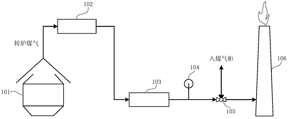
However, there are several problems in the recovery and utilization process of converter gas: 1. The gas is not up to the standard due to its composition (CO%≤35%, O 2 % ≥ 2%) and the ignition and emission is still relatively serious, the resulting energy waste and air pollution cannot be underestimated; Additional consumption of large amounts of steam (or N 2 ) and fuel; 3. CO and CO in converter gas 2 The sum of the contents can be as high as 90%, which has the natural advantage of carbon enrichment. However, due to the use of air for combustion in traditional combustion methods, the CO in the flue gas 2 By a lot of N 2 diluted, thereby losing the advantage of carbon enrichment, making CO 2 4. Based on the traditional combustion method, the combustion of the released gas will produce a large amount of NO X 5. There is a contradiction between the intermittency of converter gas and the continuity required by the energy utilization process
[0004] When implementing the above-mentioned converter gas treatment method, the inventor found that at least the following problems existed in the above-mentioned prior art: directly igniting and releasing the converter gas seriously wastes fuel, deteriorates the atmospheric environment, and also consumes a large amount of purge gas and ignition combustion-supporting gas. It can be seen that it is very unreasonable to ignite and disperse

Method used


Image

  • Diffused gas utilizing system and method
  • Diffused gas utilizing system and method
  • Diffused gas utilizing system and method

Examples


Embodiment Construction

[0046] Taking the converter gas release as an example, the present invention will be further described in detail in conjunction with the accompanying drawings and embodiments. Other forms of release gas or combustion tail gas can replace the converter gas release in the following embodiments.

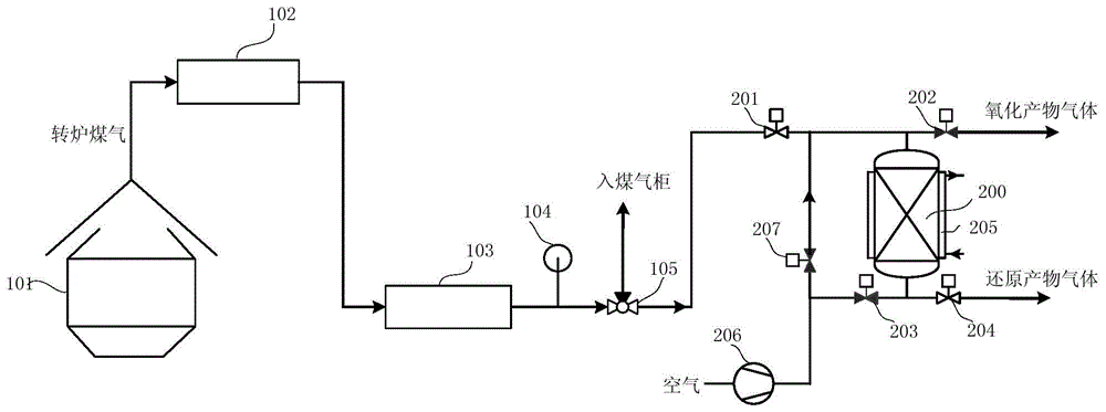
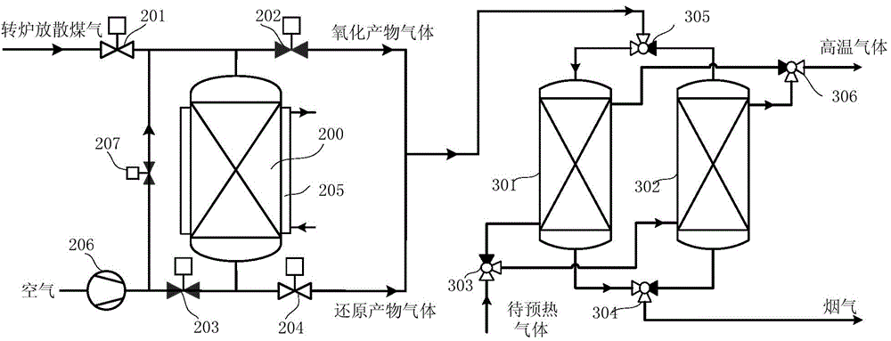
[0047] like figure 2 Shown is a schematic diagram of a converter gas utilization system provided by an embodiment of the present invention. According to the utilization system of the converter gas released by the present invention, it is connected to the release side of the three-way valve 105 to process and utilize the converter gas that was originally directly ignited and released. The system for utilizing the blown gas from the converter includes a chemical looping combustion reactor 200, and the chemical looping combustion reactor is filled with an oxygen carrier. The chemical looping combustion reactor is connected with a first input pipeline, a first output pipeline, a second in...


PUM


Abstract

The invention relates to a diffused gas utilizing system and method. The diffused gas utilizing system comprises a chemical-looping combustion reactor. The chemical-looping combustion reactor is filled with metal oxygen carriers. Diffused gas is fed into the chemical-looping combustion reactor and reacts on the oxygen carriers. The oxygen carriers are mainly composed of Fe-based oxygen carriers, and Cu-based carriers are added according to a certain proportion. The flowing direction of the diffused gas and the flowing direction of air in the chemical-looping combustion reactor are made opposite through switching of a valve, so that the problem that the diffused gas cannot be used easily due to the facts that the potential safety hazards are large and the diffused gas is exhausted intermittently is solved, and accordingly safe, clean and efficient utilization of the diffused gas is achieved.

Description

technical field [0001] The invention relates to the field of tail gas treatment, in particular to a system and method for utilizing diffused gas. Background technique [0002] In the process of iron and steel production, the efficient utilization of converter gas is related to the economic benefits and environmental responsibilities of enterprises. However, there are several problems in the recovery and utilization process of converter gas: 1. The gas is not up to the standard due to its composition (CO%≤35%, O 2 % ≥ 2%) and the ignition and emission is still relatively serious, the resulting energy waste and air pollution cannot be underestimated; Additional consumption of large amounts of steam (or N 2 ) and fuel; 3. CO and CO in converter gas 2 The sum of the contents can be as high as 90%, which has the natural advantage of carbon enrichment. However, due to the use of air for combustion in traditional combustion methods, the CO in the flue gas 2 By a lot of N 2 dil...

Claims


Application Information

Patent Timeline
IPC IPC(8): F23D14/66C21C5/38
CPCY02E20/34
Inventor 苏庆泉朱探金吴举茂
Owner UNIV OF SCI & TECH BEIJING
Learn More