Safety monitoring system for programmable logic controller in industrial control system and method thereof

A technology of industrial control system and safety monitoring system, which is applied in the direction of program control in sequence/logic controller, general control system, control/regulation system, etc., and can solve the problem of tampering and the lack of security solutions for lower computer programmable logic controllers , On-site device status information is unreliable, etc., to achieve good compatibility

Active Publication Date: 2016-02-03
BEIJING UNIV OF TECH
View PDF6 Cites 24 Cited by
  • Summary
  • Abstract
  • Description
  • Claims
  • Application Information

AI Technical Summary

Problems solved by technology

Stuxnet virus is an industrial control system virus specially written for Siemens S7 series. It will not only tamper with the configuration software in the host computer, but also tamper with the execution program written by the user, making the status information of the field equipment obtained from the configuration unreliable, and it will directly Infect the code execution part in the programmable logic controller, so that its communication function and logic function are tampered with, resulting in the occurrence of on-site security incidents
[0004] Although most of the existing PLCs have security functions, most of them are designed for their functional logic, such as personnel access control, safe execution time, safe physical execution environment, etc. The means of attack cannot be detected and defended at all
Existing means to ensure the security of industrial control systems include safe industrial control protocols, host computer malicious code defense, and real-time monitoring of field device status, etc. There is no effective security solution for the relatively closed lower computer programmable logic controller

Method used


Image

  • Safety monitoring system for programmable logic controller in industrial control system and method thereof
  • Safety monitoring system for programmable logic controller in industrial control system and method thereof
  • Safety monitoring system for programmable logic controller in industrial control system and method thereof

Examples


Embodiment Construction

[0053] The present invention will be described in further detail below in conjunction with the accompanying drawings and specific embodiments of the description

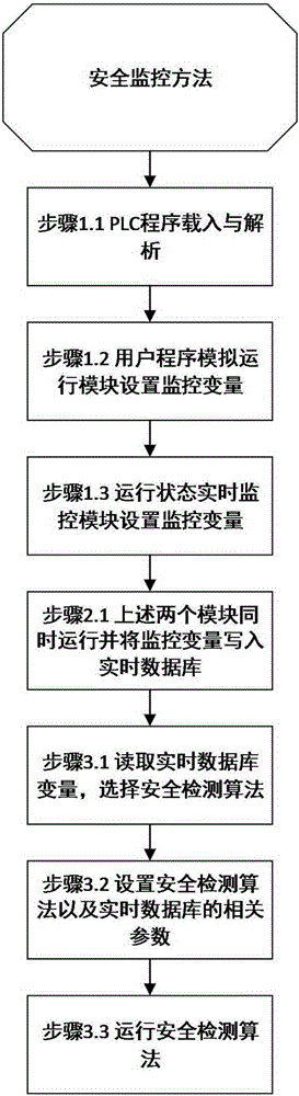
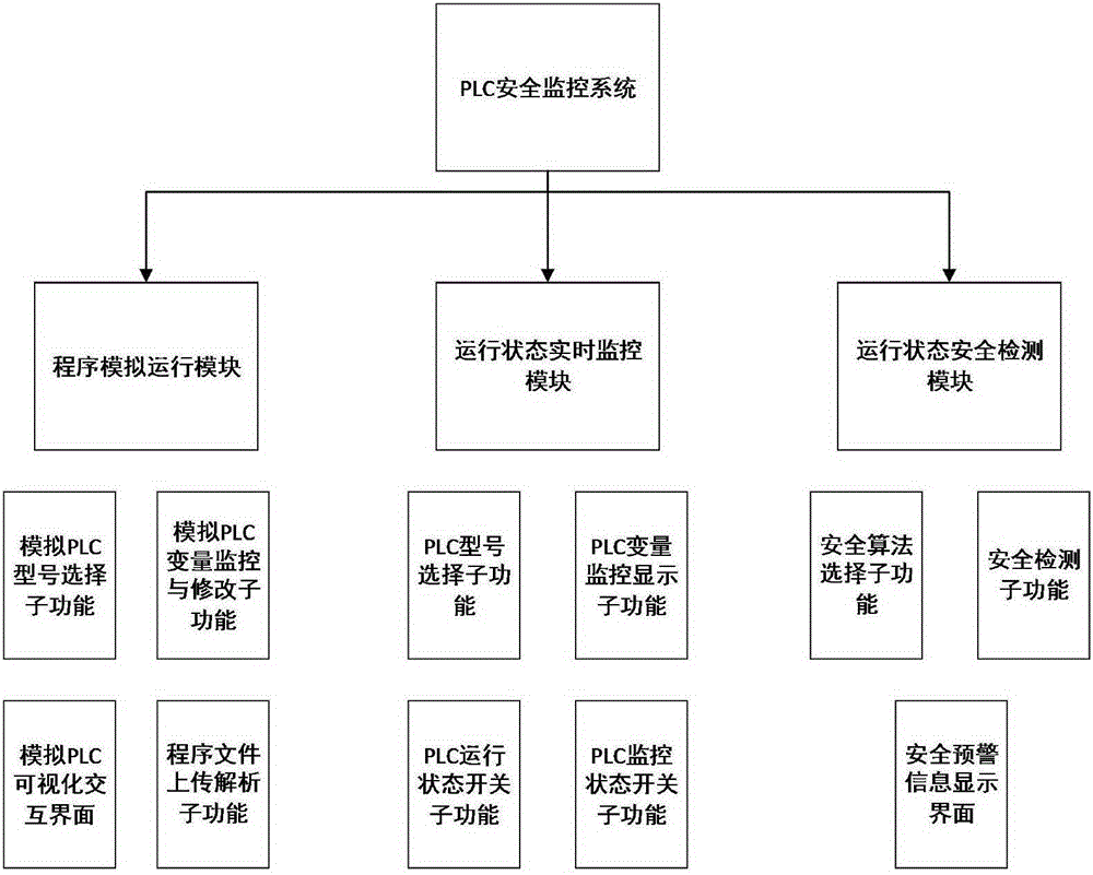
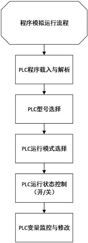
[0054] figure 2 It describes the structure diagram of the PLC safety monitoring system, including three modules: user program simulation operation module, real-time monitoring module of running status and safety detection module of running status. Among the three modules, the user program simulation running module and the running status real-time monitoring module can run independently, and the running status safety detection module must use the output of the first two modules as input to get the correct result. Below the present invention will do the elaboration of specific implementation mode with Siemens S7-200 series PLC, simplify flow process as Figure 3.1-3.3 shown.

[0055] The main function of the user program simulation operation module described here is to read in the AWL file exported by the STEP7 prog...


PUM


Abstract

The invention provides a safety monitoring system for a programmable logic controller in an industrial control system and a method thereof. The system is composed of a user program simulation operation module, an operation state real-time monitoring module and an operation state safety detection module based on a real-time database. When safety detection is not performed, the user program simulation operation module can independently operate for simulation operation of the PLC, and operation state real-time monitoring module can independently operate for remote monitoring of input and output and the variable values of the PLC. When a safety detection function is started, the three modules are connected and interact via the real-time database, the monitoring variables outputted by the user program simulation operation module and the operation state real-time monitoring module are inputted to the real-time database, and the operation state safety detection module reads the corresponding variables from the real-time database for safety detection.

Description

technical field [0001] The present invention relates to the field of industrial control and information technology, in particular to a system and method for safety monitoring of the operating state of a programmable logic controller (PLC) in an industrial control system, and takes Siemens S7-200 as an example to carry out the system design and method verify. Background technique [0002] With the continuous cross-integration of industrialization and informatization, more and more information technologies have been applied to the industrial field. At present, industrial control systems have been widely used in electric power, water power, petrochemical, pharmaceutical, food manufacturing, transportation, aerospace and other industrial fields. Among them, more than 80% of the key infrastructure related to the national economy and people's livelihood rely on industrial control systems to realize automatic operations. The industrial control system has become an important part o...

Claims


Application Information

Patent Timeline
IPC IPC(8): G05B19/05G05B19/048
CPCG05B19/048G05B19/058G05B2219/14006
Inventor 詹静吴欢赵勇
Owner BEIJING UNIV OF TECH
Why Eureka
Try Eureka