Binding method of large-sized transformer iron core and special tool for large-sized transformer iron core

A technology for transformers and iron cores, which is applied in the manufacture of inductors/transformers/magnets, transformer/inductor cores, electrical components, etc. It can solve problems such as inability to tighten the effect, low binding force, and small binding force of the binding structure, and achieve good results. Encircling the binding effect, reducing the cost of tooling, and the effect of strong binding integrity

Inactive Publication Date: 2016-02-03
TIANWEI BAOBIAN QINHUANGDAO TRANSFORMER
View PDF6 Cites 3 Cited by
  • Summary
  • Abstract
  • Description
  • Claims
  • Application Information

AI Technical Summary

Problems solved by technology

[0002] The binding of the center column and the side yoke in the assembly process of the large-scale transformer core is manually operated. The binding of the core column in the background technology uses a commercially available binding belt, which has a small binding force, a single stress point, and is easy to deform and break. After tightening about 10 pieces of clamping equipment (aircraft clamps, shoulder pole clamps), and then use about 10 commercially available binding ties at intervals to meet the clamping force requirements, the operation is cumbersome and inefficient, and at least 4 people are required to operate at the same time. Finish
The overall shape of the large-scale transformer core column is a cylinder. The clamping tools (aircraft clamps, pole clamps) used in the background technology are not special tools, and can only be stacked and pressed in one direction in the thickness direction, which cannot effectively tighten the embrace effect, background technology The binding force of the binding structure is small, and only plays an auxiliary fastening role

Method used


Image

  • Binding method of large-sized transformer iron core and special tool for large-sized transformer iron core
  • Binding method of large-sized transformer iron core and special tool for large-sized transformer iron core

Examples


Embodiment Construction

[0029] Hereinafter, the present invention will be further described through embodiments in conjunction with the drawings.

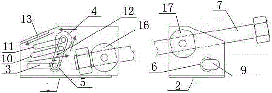
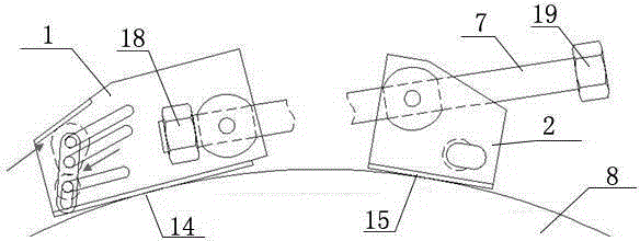
[0030] A special tooling for lashing large transformer cores, including: main body 1 and slide rail 3, slide 1 4, slide 2 5, slide 2 10, slide 3 11, and inclined end surface 13 arranged on the main body 1. , Screw sleeve one 16 and nut one 18; main body two 2 and the pin opening 6, pin 9, screw sleeve two 17 and nut two 19 arranged on the main body two; screw 7 connecting main body one 1 and main body two 2;

[0031] The slide rail two 10 on the left part of the main body 1 is arranged in parallel with the slide rail three 11, the left end of the slide rail two 10 is close to the slide rail 1-3, the left end of the slide rail three 11 is close to the inclined end surface 13; the slide rail 1-4 is on the slide rail Slide two 10 and slide three 11 slide, slide two 5 slide in slide one 3, slide one 4 and slide two 5 are connected together by connecting plate 12; ...


PUM


Abstract

The invention relates to a binding method of a large-sized transformer iron core and a special tool for the large-sized transformer iron core, and belongs to the technical field of the production of a transformer. According to the technical scheme, the method comprises: connecting the head end of a binding tape to a dowel (9), matching the dowel with a lock-joint (6) in a main body II, straining the binding tape to enable the dowel to slide into the lock-joint to be locked; penetrating the tail end of the binding tape into a slide block I (4) and a slide block II (5) from the part between a slide rail I (3) and a slide rail II (10) on the main body I, bypassing the slide block I, then enabling the binding tape to stretch out of the main body I from the part between a slide rail III (11) and a bevel end surface (13), and extracting the excessive binding tape completely from the end of the main body I; and tightening a nut II (19) of a screw (7) by utilizing a wrench, shortening the distance between the main body I and the main body II to achieve binding and straining. The binding method has positive effects that the binding coercivity is high, multiple points are stressed simultaneously, stability and firmness are realized, the binding integrity is high, no additional clamping tool is needed, the operation is simple, and the binding work can be completed only by two persons at most.

Description

Technical field [0001] The invention relates to a binding method and special tooling for a large transformer core, which is used for binding a central column and a side yoke in the assembly process of a large transformer core, and belongs to the technical field of transformer production. Background technique [0002] The tying of the center column and side yoke of the large transformer iron core assembly process adopts manual operation. The iron core column of the background technology adopts commercially available lashing tape, which has low lashing force, single stress point, easy deformation and breakage, and needs to be used at the same time during operation. After about 10 pieces of clamping tooling (aircraft clip, pole clip) are tightened, about 10 commercially available lashing straps are used at intervals to meet the clamping force requirements. The operation is cumbersome and the efficiency is low. At least 4 people are required to operate at the same time. carry out. T...

Claims


Application Information

Patent Timeline
Patent Type & Authority Applications(China)
IPC IPC(8): H01F41/02H01F27/26
Inventor 卢嘉伟卢宁李红军王洋董杰杜丽华
Owner TIANWEI BAOBIAN QINHUANGDAO TRANSFORMER
Why Eureka
Try Eureka