
Shallow trench isolation structure formation method

An isolation structure, shallow trench technology, used in electrical components, semiconductor/solid-state device manufacturing, circuits, etc.

Inactive Publication Date: 2016-02-03
ACM RES SHANGHAI
View PDF4 Cites 1 Cited by
  • Summary
  • Abstract
  • Description
  • Claims
  • Application Information

AI Technical Summary

Problems solved by technology

Since SC1 does not chemically react with silicon dioxide, even if there is silicon dioxide residue on the surface of the silicon nitride layer, SC1 is powerless

Method used


Image

  • Shallow trench isolation structure formation method
  • Shallow trench isolation structure formation method
  • Shallow trench isolation structure formation method

Examples


Embodiment Construction

[0025] In order to describe the technical content, achieved goals and effects of the present invention in detail, the following will be described in detail in conjunction with the embodiments and accompanying drawings.

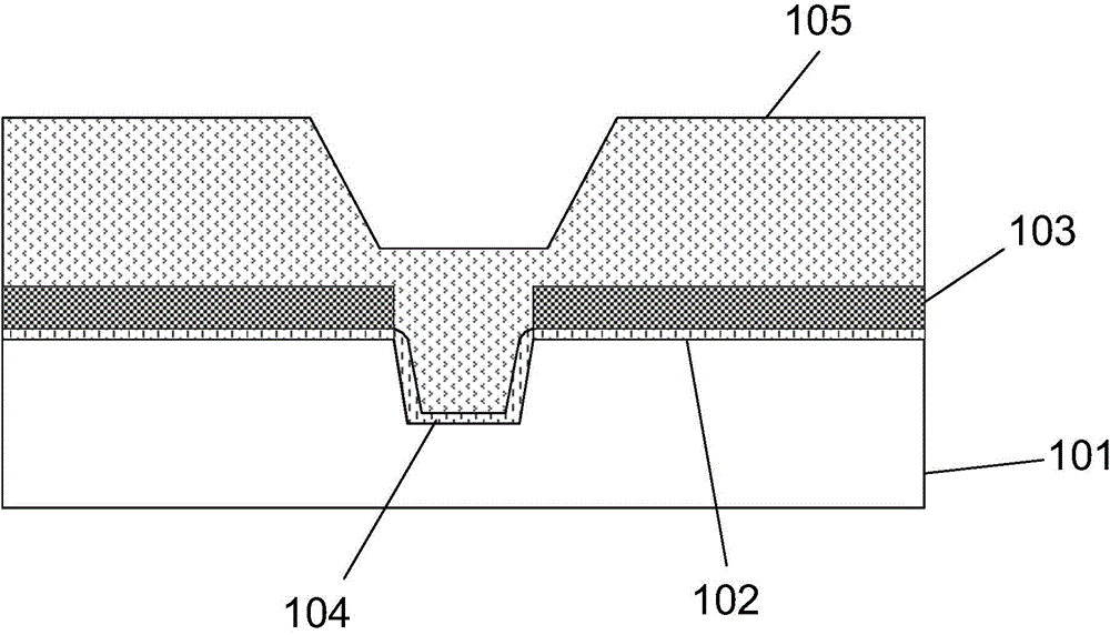
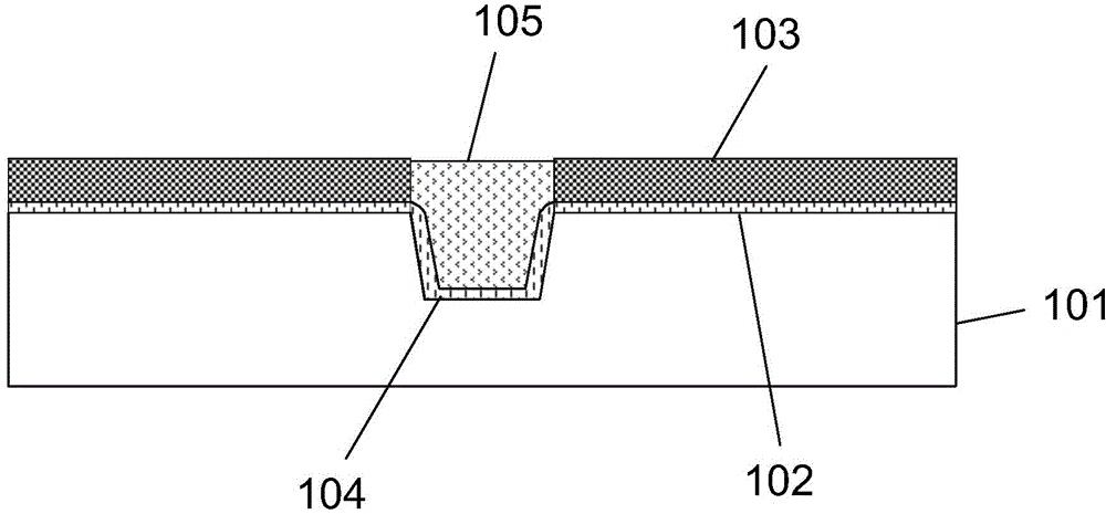
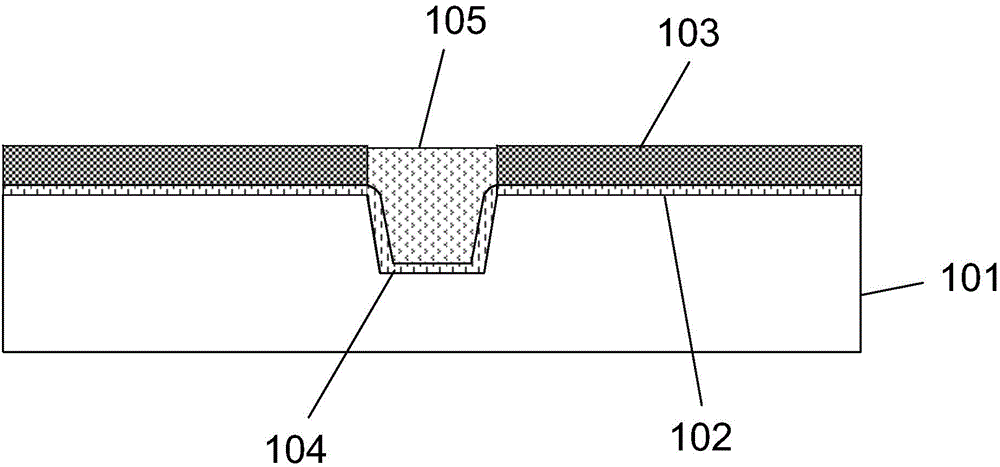
[0026] refer to Figure 1(a) to Figure 1(c) as well as figure 2 As shown, a method for forming a shallow trench isolation structure according to an embodiment of the present invention is disclosed. The method comprises the steps of:

[0027] Step S201, providing a semiconductor substrate 101, and growing a pad oxide layer 102 on the surface of the semiconductor substrate 101;

[0028] Specifically, the semiconductor substrate 101 is a silicon substrate, and the pad oxide layer 102 is made of silicon dioxide.

[0029] Step S202, depositing a silicon nitride layer 103 on the surface of the pad oxide layer 102;

[0030] Specifically, the silicon nitride layer 103 serves as a stop layer for subsequent chemical mechanical polishing and planarization.

[0031] ...


PUM


Abstract

The invention discloses a shallow trench isolation structure formation method which comprises the following steps: providing a semiconductor substrate, and growing a pad oxide layer on the surface of the semiconductor substrate; depositing a silicon nitride layer on the surface of the pad oxide layer; etching the silicon nitride layer, the pad oxide layer and the semiconductor substrate in sequence to form a shallow trench; growing a liner oxide layer on the bottom and side wall of the shallow trench; depositing a silicon dioxide dielectric layer on the surface of the silicon nitride layer and in the shallow trench; carrying out planarization processing on the silicon dioxide dielectric layer until the silicon nitride layer by adopting the chemico-mechanical polishing technology; cleaning the surface of the silicon nitride layer by adopting BHF; and removing the silicon nitride layer. According to the method, the surface of the silicon nitride layer is cleaned by adopting the BHF after carrying out chemico-mechanical polishing on the silicon dioxide dielectric layer, and the BHF has chemical reaction with the silicon dioxide, thereby preventing the silicon dioxide from being residual on the surface of the silicon nitride layer, and ensuring that the silicon nitride layer can be fully removed without having silicon nitride residual in the follow-up silicon nitride removing.

Description

technical field [0001] The invention relates to the technical field of semiconductor structure manufacturing, in particular to a method for forming a shallow trench isolation structure. Background technique [0002] At present, shallow trench isolation technology has become the mainstream isolation technology for 0.25um and below processes. The existing method for forming a shallow trench isolation structure includes the following steps: [0003] First, a silicon dioxide underlayer is grown on a silicon substrate; [0004] Then, a silicon nitride layer is deposited on the surface of the silicon dioxide pad layer, and the silicon nitride layer is used as a stop layer for subsequent chemical mechanical polishing; [0005] Next, sequentially etch the silicon nitride layer, silicon dioxide pad layer and silicon substrate to form shallow trenches; [0006] Subsequently, a silicon dioxide liner is grown on the bottom and sidewalls of the shallow trench; [0007] Then, use high...

Claims


Application Information

Patent Timeline
IPC IPC(8): H01L21/762
Inventor 杨贵璞王坚王晖
Owner ACM RES SHANGHAI
Learn More