A single wire transfer device and an integrated wire transfer device composed of the same

A wire transfer and transfer device technology, applied in the direction of coupling device, circuit, connection, etc., can solve the problems of galvanic corrosion at copper-aluminum joints, scattered wires of multiple strands, and mismatched interfaces, so as to achieve strong adaptability and continuous connection. High line efficiency and guaranteed electrical performance

Active Publication Date: 2018-06-08
GUANGZHOU PANYU CABLE WORKS
View PDF5 Cites 0 Cited by
  • Summary
  • Abstract
  • Description
  • Claims
  • Application Information

AI Technical Summary

Problems solved by technology

[0010] One of the tasks of the present invention is to provide a single wire transfer device to solve the above-mentioned interface mismatch, the possibility of galvanic corrosion at the copper-aluminum connection, and the possibility of damaging the wire or causing the multi-strand wires to scatter when the compression screw is directly pressed. problem, the specific solution adopted is:

Method used


Image

  • A single wire transfer device and an integrated wire transfer device composed of the same
  • A single wire transfer device and an integrated wire transfer device composed of the same
  • A single wire transfer device and an integrated wire transfer device composed of the same

Examples


Embodiment 1

[0048] Preferred embodiment 1: Single wire transfer device for the wiring hole of the electric meter (double extrusion block scheme)

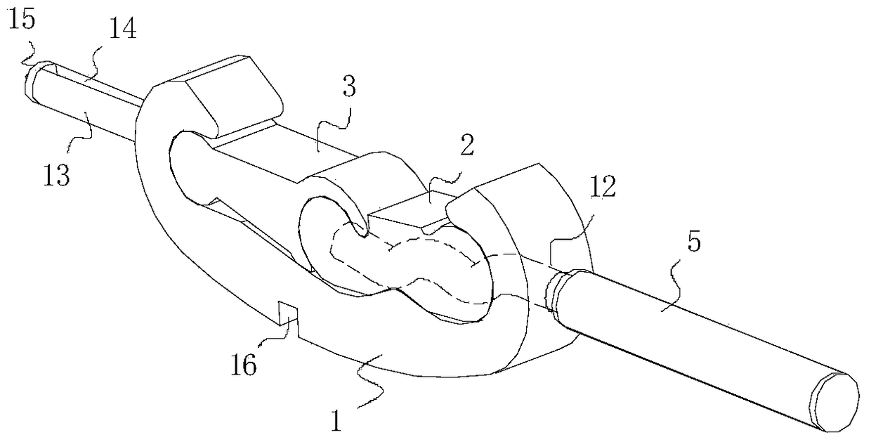
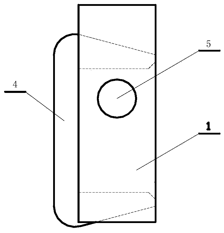
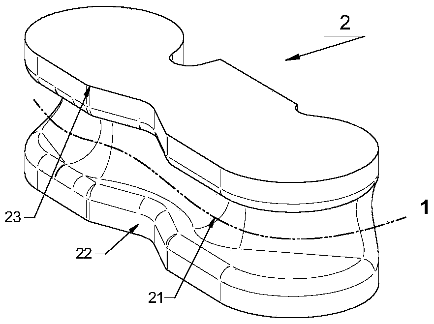
[0049] Figure 1-Figure 6 It is a schematic diagram of preferred embodiment 1 of the present invention. read figure 1 , Figure 5 and Figure 6 It can be seen that the wire transfer device disclosed in this embodiment includes a transfer device body 1 , a first extruding block 2 , a second extruding block 3 and a "ㄈ"-shaped locking member 4 .

[0050] The adapter body 1 is provided with an accommodating cavity 11 , a wire insertion hole 12 and a plug terminal 13 . The insertion terminal 13 is provided with a V-shaped groove 14 and a nail portion 15 . Among them: the V-shaped groove 14 is used to cooperate with the compression screw of the power equipment or the electromechanical product to realize the fixation between the plug-in terminal 13 and the wiring hole, that is, the V-shaped groove is the screw coordination structure of this embo...

Embodiment 2

[0061] Preferred Embodiment 2: A single wire transfer device for the wiring hole of an electric meter (three-extrusion block scheme)

[0062] Figure 7 It is a schematic diagram of a single wire transfer device composed of three extruded blocks. read Figure 7 It can be seen that the embodiment using three extruding blocks includes the adapter body 10, the first extruding block 20 close to the wire insertion hole, the second extruding block 30 close to the plug terminal, and the third extruding block 50 in the middle. and locking screw 40. The adapter body 10 is provided with an accommodating cavity for accommodating three extruded blocks, a wire insertion hole 102 and a plug terminal 103 for connecting to the wiring holes of electric equipment or electromechanical products. The plug terminal 103 is a cylinder with a V-shaped groove 104 , and the plug portion of the plug terminal 103 is provided with a nail portion 105 . The two ends of the accommodating cavity are provide...

Embodiment 3

[0065] Preferred embodiment 3: the single body of the crimping groove lengthened type wire transfer device

[0066] Figure 8 It is a schematic structural diagram of a single wire transfer device disclosed in the third preferred embodiment of the present invention. read Figure 8 It can be seen that the cable transfer device with lengthened crimping groove includes a transfer device body 100 , a first extruding block 200 and a second extruding block 300 . The adapter body 100 is provided with an accommodating cavity 1001 , a wire insertion hole 1002 , a plug terminal 1003 , a V-shaped groove 1004 formed on the plug terminal, and a staple portion 1005 provided at the plug portion of the plug terminal. Both ends of the accommodating cavity 1001 are C-shaped structures 1007, and the bottom of the accommodating cavity 1001 is sequentially provided with a first convex portion 1008, a first concave portion 1009, and a second convex portion from the wire insertion hole 1002 to the ...


PUM


Abstract

A wire transfer device unit and a multi-unit integrated wire transfer device composed of it, the wire transfer device unit includes a transfer device body and at least two extruded blocks, and the at least two extruded blocks The pressing block is installed in the body of the adapter device; the body of the adapter device and the extruding block and the extruding blocks are rotatably connected; the extruding block can be compressed or loosened when rotating Open the wires to be connected; the body of the adapter device is also provided with plug-in terminals for plugging into wiring holes of electric equipment or electromechanical products. The integrated wire transition device includes an insulating housing and at least two wire transition device units arranged in the insulating housing. The single wire transfer device and the integrated wire transfer device proposed by the present invention have simple wiring, high construction efficiency, reliable connection, guaranteed electrical performance, and can meet the connection requirements of cables with different diameters.

Description

technical field [0001] The invention belongs to the field of electrical connection technology, and specifically relates to a single wire transfer device for connecting wires to wiring holes of electric equipment or electromechanical products and a multi-unit integrated wire transfer device composed of the same. Background technique [0002] When the existing power equipment or mechanical and electrical products are connected to the power line, the electrical connection between the wire and the internal circuit is usually established by using a wiring hole and a compression screw. Such as Figure 11 and Figure 12 As shown, the wiring structure of electric equipment or electromechanical products generally includes shell wiring holes 10', compression screws 20' and connection terminals 30', wherein: connection terminals 30' are used to connect internal circuits and external cables, and compression The screw 20' is used to compress the wire to the terminal 30', and the housing...

Claims


Application Information

Patent Timeline
Patent Type & Authority Patents(China)
IPC IPC(8): H01R13/02H01R4/50H01R27/00
Inventor 胡超强尤占山安向阳覃丹王利江卢广业张仕欢申常伟陈雪儿何平
Owner GUANGZHOU PANYU CABLE WORKS
Why Eureka
Try Eureka