Crankshaft cleaning machine

A cleaning machine and crankshaft technology, applied in cleaning methods and utensils, cleaning methods using liquids, chemical instruments and methods, etc., can solve the problems of deviation of the pressure head from the original working position, insufficient cleaning pressure, and small diameter of the crankshaft oil passage, etc. Achieve the effect of avoiding cleaning blind spots, avoiding ineffective cleaning, and reducing production costs

Active Publication Date: 2016-02-10
CHONGQING KEBEN TECH
View PDF6 Cites 27 Cited by
  • Summary
  • Abstract
  • Description
  • Claims
  • Application Information

AI Technical Summary

Problems solved by technology

In the process of cleaning the crankshaft of the existing crankshaft cleaning machine, due to insufficient cleaning pressure, the crankshaft after cleaning is often not clean, and there are many residues, which affects the quality of large engine products. In addition, the jet compaction in the existing cleaning machine Due to the need for continuous lifting operation of the mechanism, the pressure head deviates from the original working position, and the jet cannot fully enter the oil passage hole and leak, thus affecting the cleanliness
The relative positions and hole diameters of the oil passage holes of crankshafts of different specifications are different. The oil passage holes of crankshafts are small and deep. During the processing process, there may be burrs and chip clogging. The existing cleaning machine cannot realize fast cleaning of the holes.
Especially the existing cleaning machines, usually only one cleaning machine can clean crankshafts of one specification, and different cleaning machines are designed for crankshafts of different specifications. There are many specifications of crankshafts, and there are many cleaning machines, and the cost is relatively high. A Cleaning Machine Adaptable to Various Specifications of Crankshafts

Method used


Image

  • Crankshaft cleaning machine
  • Crankshaft cleaning machine
  • Crankshaft cleaning machine

Examples


Embodiment

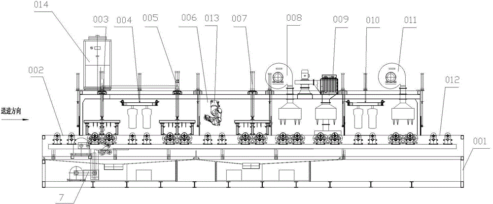
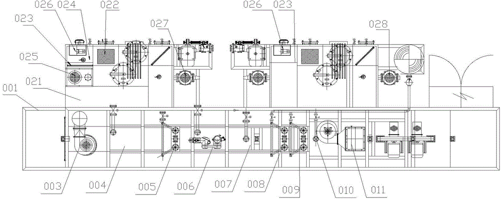
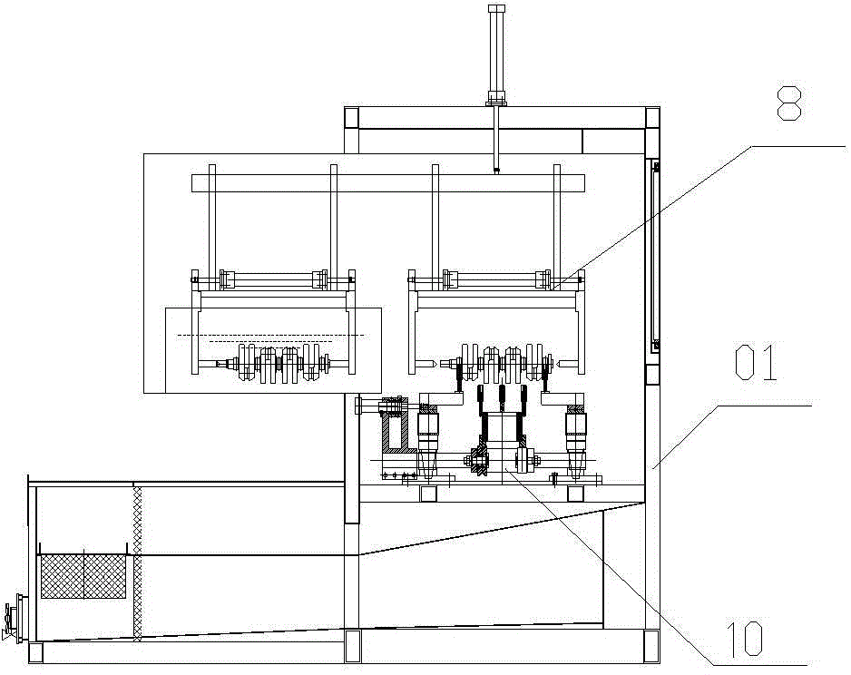
[0108] Such as Figure 1 to Figure 3 As shown, the present invention provides a rough cleaning machine for crankshafts, including a frame 001, a sealing cover (not shown) covered on the frame 001, and a feeding station sequentially arranged on the frame 001 according to the cleaning sequence 002, the first surface cleaning system 003, the surface ultrasonic cleaning system 004, the second surface cleaning system 005, the oil passage cleaning system 006, the surface rinsing system 007, the surface drying system 008, the hot air drying system 009, the ultrasonic oil immersion system 010 , wind cutting oil blowing system 011 and unloading station 012.

[0109] The first surface cleaning system 003, the second surface cleaning system 005, and the surface rinsing system 007 are equipped with spray cleaning rooms, ultrasonic cleaning systems, surface drying systems 008, hot air drying systems 009, ultrasonic oil immersion systems 010, wind cutting blowing The oil system 011 is resp...


PUM


Abstract

The invention provides a crankshaft cleaning machine. The crankshaft cleaning machine comprises a rack as well as a first surface cleaning system, a surface ultrasonic cleaning system, a second surface cleaning system, an oil duct cleaning system, a surface rinsing system, a surface blow-drying system, a hot air drying system, an ultrasonic oil immersion system and a wind-shear oil blowing system which are arranged on the rack sequentially, a workpiece conveying system for conveying workpieces is further arranged on the rack and comprises a lifting and conveying mechanism and a tool adjusting mechanism. The crankshaft cleaning machine is designed for cleaning an automobile crankshaft and integrates advanced combined means such as ultrasonic waves, high-pressure spray, ultrahigh-pressure spray, rotation, flexible robot hole alignment, ultrasonic oil immersion, oil blowing and the like so as to be applied to crankshaft cleaning, drying and rustproofing processes, and the tool adjusting mechanism of the conveying system can adjust the width automatically to adapt to cleaning of products in various specifications.

Description

technical field [0001] The invention belongs to the technical field of crankshaft cleaning devices, in particular to a crankshaft cleaning machine. Background technique [0002] Before the crankshaft leaves the factory, the surface and oil hole of the crankshaft must be cleaned to ensure the quality requirements of the engine product. In the process of cleaning the crankshaft of the existing crankshaft cleaning machine, due to insufficient cleaning pressure, the crankshaft after cleaning is often not clean, and there are many residues, which affects the quality of large engine products. In addition, the jet compaction in the existing cleaning machine Due to the need for continuous lifting operation of the mechanism, the pressure head deviates from the original working position, and the jet cannot fully enter the oil passage hole and leak, thus affecting the cleanliness. The relative positions and diameters of the oil passage holes of crankshafts of different specifications ...

Claims


Application Information

Patent Timeline
Patent Type & Authority Applications(China)
IPC IPC(8): B08B3/02B08B3/10B08B3/12B08B3/14B08B13/00B05C13/00B05C7/04B05C11/10
Inventor 余虹江朱兴德刘建晏增盛何传
Owner CHONGQING KEBEN TECH
Why Eureka
Try Eureka