Machining method of turbine working blade

A processing method and blade technology, which are applied in the field of aero-engine process equipment and manufacturing, can solve the problems of incorrect determination of the blade profile reference, position degree and installation angle out of tolerance, etc., and achieve the effects of improving accuracy, reducing times and eliminating errors.

Active Publication Date: 2016-02-10
CHINA HANGFA SOUTH IND CO LTD
View PDF6 Cites 26 Cited by
  • Summary
  • Abstract
  • Description
  • Claims
  • Application Information

AI Technical Summary

Problems solved by technology

[0006] The invention provides a processing method of turbine working blades to solve the existing technical problems of the existing turbine working blade processing methods, such as the problem of out-of-tolerance position and installation angle, and the technical problems of misjudgment of the blade profile reference by tenon tooth displacement.

Method used


Image

  • Machining method of turbine working blade
  • Machining method of turbine working blade
  • Machining method of turbine working blade

Examples


Embodiment Construction

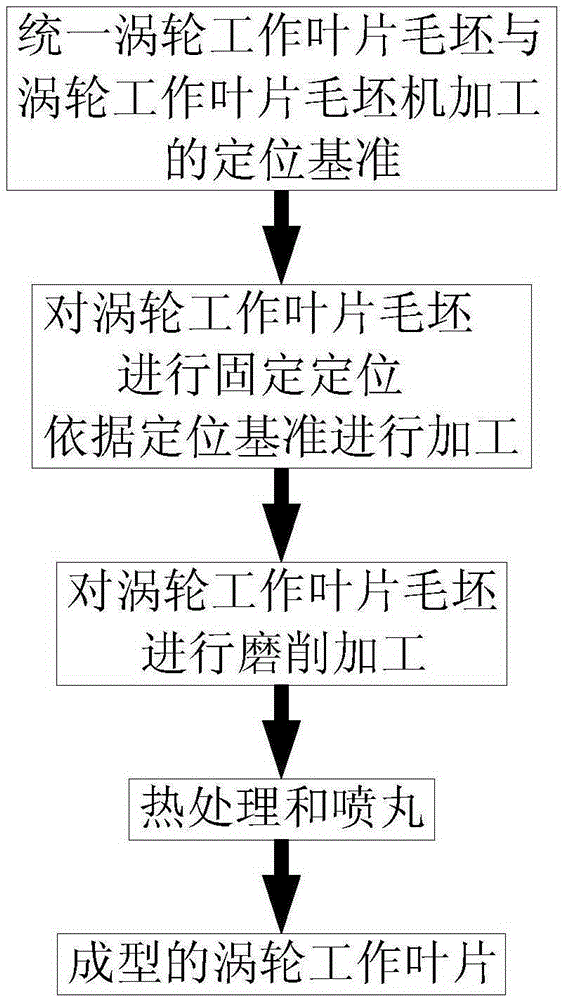
[0032] The embodiments of the present invention will be described in detail below with reference to the accompanying drawings, but the present invention can be implemented in various ways defined and covered below.

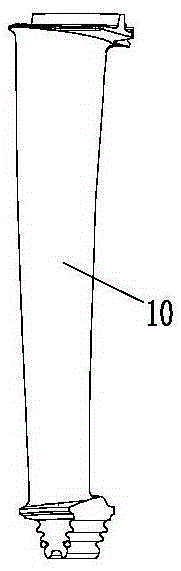
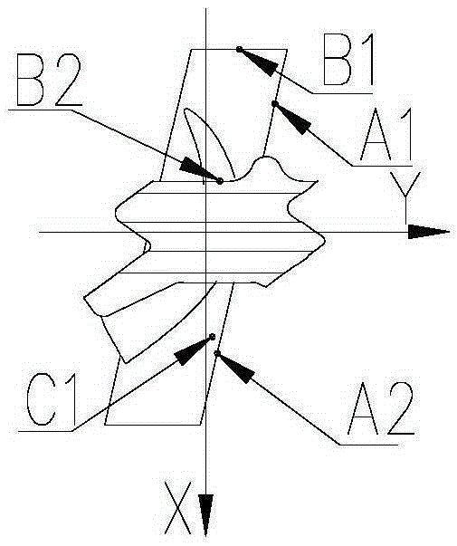
[0033] figure 1 It is a structural block diagram of a machining method for a turbine working blade in a preferred embodiment of the present invention; figure 2 It is a structural schematic diagram of a turbine working blade blank in a preferred embodiment of the present invention; image 3 It is one of the schematic structural diagrams of the establishment of five points and one line in the preferred embodiment of the present invention; Figure 4 It is the second structural diagram of the establishment of five points and one line in the preferred embodiment of the present invention; Figure 5 It is a structural schematic diagram of the clamping fixture when processing tenon teeth according to the preferred embodiment of the present invention; Image 6 Yes Fi...


PUM


Abstract

The invention discloses a machining method of a turbine working blade, which comprises the following steps: a, unifying positioning standards of a turbine working blade blank and turbine working blade machining; b, fixing and positioning the turbine working blade blank, and performing machining according to the positioning standards; c, performing grinding to form tenon teeth, positioning machined tenon teeth, machining an upper edge plate and a lower edge plate of the turbine working blade and sawteeth of a blade tip shroud; and d, performing heat treatment and shot blasting of the machined turbine working blade to form the turbine working blade. Machining and blank standards are unified to realize the consistency of a blank mould positioning point and a machined tenon positioning point, so that an error caused by standard disunity is eliminated, the frequency of standard conversion is reduced, the conversion precision is increased, and the designed blade profile positional tolerance requirement is met; and the precision of coordinate positional tolerance evaluated by building a standard after machining is improved. The machining method is suitable for technological equipment and manufacturing of aero-engine turbine working blades.

Description

technical field [0001] The invention relates to the field of aero-engine process equipment and manufacturing technology, in particular, to a processing method for turbine working blades. Background technique [0002] The new engine blades have brought new difficulties to the processing technology while improving the performance of the engine. In mechanical processing, the blade position, installation angle, blade crown sawtooth and other dimensions are related to each other, and the precision is high, so it is difficult to be fully qualified. The important factor is the difficulty of precise positioning, and the cumulative error after multiple conversions from blank to machining has exceeded the accuracy requirements of the blade itself. These have become key factors restricting product quality and pass rate at this stage. [0003] The new type of engine blade has a complex design structure, the blade body is a space curved surface, the tenon teeth are a fir tree structure,...

Claims


Application Information

Patent Timeline
Patent Type & Authority Applications(China)
IPC IPC(8): B23P15/02
CPCB23P15/02
Inventor 初文潮易鹏黄文俊杨锦尹准周红梅
Owner CHINA HANGFA SOUTH IND CO LTD
Why Eureka
Try Eureka