Method and device for controlling the negative pressure on a thread catching or cleaning nozzle of a workstation of a textile machine

A yarn catcher and textile machine technology, which is applied to the negative pressure field at the yarn catcher or yarn clearer to reduce the risk of tearing and yarn breakage.

Inactive Publication Date: 2016-02-10
SAURER GERMANY GMBH & CO KG
View PDF12 Cites 2 Cited by
  • Summary
  • Abstract
  • Description
  • Claims
  • Application Information

AI Technical Summary

Problems solved by technology

In the event of a splice joint tear caused by this or other means before or at the suction area of ​​the catcher or clearer, the catcher or clearer can still suck in the upper yarn, which then causes above question

Method used


Image

  • Method and device for controlling the negative pressure on a thread catching or cleaning nozzle of a workstation of a textile machine
  • Method and device for controlling the negative pressure on a thread catching or cleaning nozzle of a workstation of a textile machine
  • Method and device for controlling the negative pressure on a thread catching or cleaning nozzle of a workstation of a textile machine

Examples


Embodiment Construction

[0037] Here, identical components are identified with the same reference symbols in all figures.

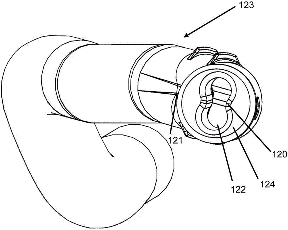
[0038] figure 1 A prior art yarn catching or clearing nozzle 123 is shown, which has a bone shape 120 in the region of the nozzle outlet. This means that the nozzle outlet is blocked in area 124 and is only open in area 122 , which is defined by the outline of bone shape 120 . The lateral constriction of the open nozzle outlet partly continues to the inside of the yarn catching nozzle or the yarn clearing nozzle, as indicated by reference numeral 121 . As mentioned above, this shape notably ensures the suction of the yarn in the form of a loop, which loop is also maintained during the suction period.

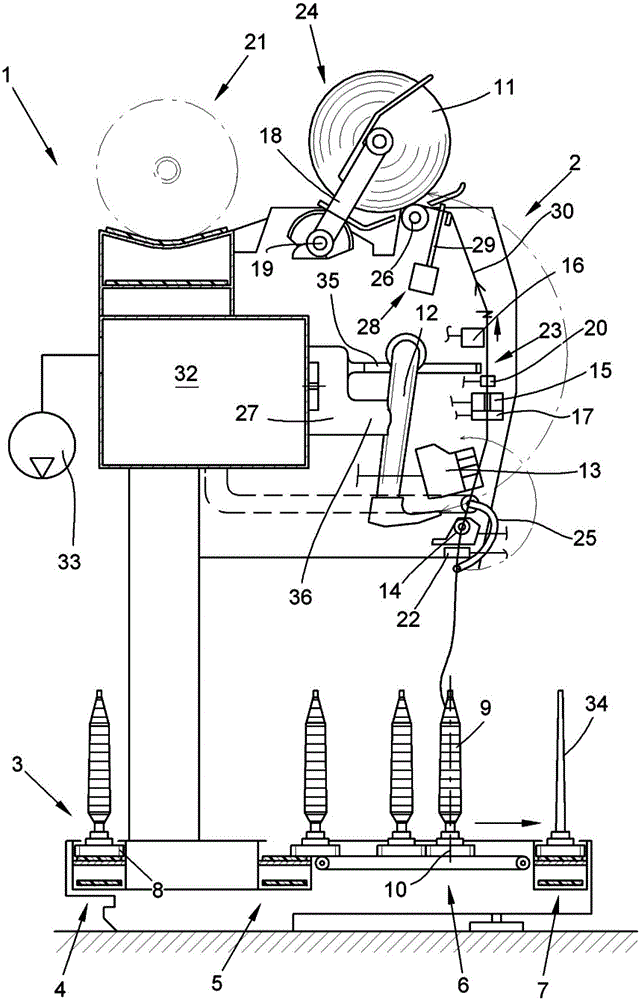
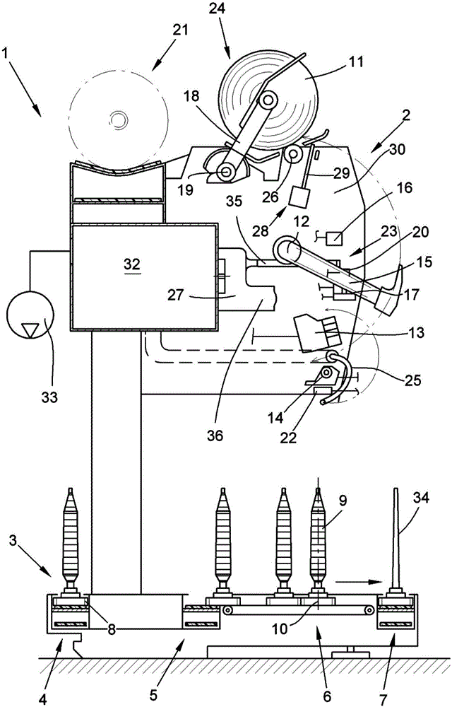
[0039] figure 2 taken from DE102005001093A1 and in this application it is stated that its figure 1 , which shows, in a schematic side view, a view of a station of a textile machine producing cross-wound bobbins, here a cross-winding winder 1 , whose yarn catcher or yarn cleare...


PUM


Abstract

The present invention relates to a method and device for controlling the negative pressure on a thread catching or cleaning nozzle (23) of a workstation (2) of a textile machine (1) in particular to a winding machine for producing winding bobbins (11), wherein the workstation (2) is provided with a thread connecting device (13) for connecting upper threads from the winding bobbins (11) to lower threads to be wound on the winding bobbins (11). The method guarantees that at least during the first phase of a winding process started after thread connection between the upper threads and the lower threads is formed to form threads (30), no negative pressure or so low negative pressure is applied to the thread catching or cleaning nozzle (23), and the thread catching or cleaning nozzle (23) does not suck in the threads during the starting phase.

Description

technical field [0001] The invention relates to a method and a device for controlling negative pressure at a yarn catching nozzle or a yarn clearing nozzle at a station of a textile machine producing winding bobbins. Background technique [0002] A textile machine for producing wound bobbins consists of a number of similar stations, each producing wound bobbins, which are supplied with energy, eg electricity, by a device centrally located on the textile machine. Such a textile machine may especially be a bobbin winder, which winds a number of spinning bobbins of smaller volume into wound bobbins containing much more yarn material, especially cross-wound bobbins, wherein the lower The yarns come from the respective spinning bobbins. But one possible application of the invention is also in winders in which the lower yarn comes from the spinning device. [0003] The stations relevant to the present invention all have a yarn splicing device, usually a splicer or a knotter, whi...

Claims


Application Information

Patent Timeline
Patent Type & Authority Applications(China)
IPC IPC(8): B65H67/08
CPCB65H54/702B65H54/88B65H67/081B65H2701/31
Inventor 亚历山大·马克思迈克尔·赖曼
Owner SAURER GERMANY GMBH & CO KG
Why Eureka
Try Eureka