High-lance-position vacuum refining method based on coherent jet top lance

A technology of vacuum refining and top gun, which is applied in the field of secondary smelting, can solve the problems that restrict the development and limitation of RH refining process, and achieve the effect of improving penetration depth and stirring intensity, uniform composition and temperature, and enhanced penetration ability

Active Publication Date: 2016-02-10
CISDI ENG CO LTD +1
View PDF11 Cites 8 Cited by
  • Summary
  • Abstract
  • Description
  • Claims
  • Application Information

AI Technical Summary

Problems solved by technology

However, the existing RH vacuum refining top gun structure limits this process requirement and restricts the development of a more efficient RH refining process. Therefore, it is necessary to study a simultaneous refining process such as oxygen blowing, powder spraying, and combustion heating. New Vacuum Refining Process and New Spray Gun Nozzle Structure

Method used


Image

  • High-lance-position vacuum refining method based on coherent jet top lance
  • High-lance-position vacuum refining method based on coherent jet top lance
  • High-lance-position vacuum refining method based on coherent jet top lance

Examples


Embodiment 1

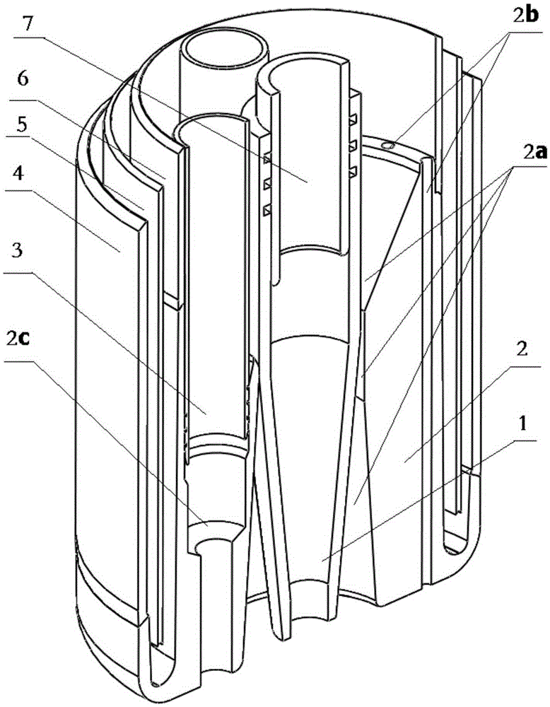
[0055] A high-lance vacuum refining method based on cluster top lances, including the use of process equipment consisting of a ladle, a vacuum chamber, a cluster top lance and a vacuum device, inserting the dipping tube of the vacuum chamber into the molten steel in the ladle, and the top lance Insert the vacuum chamber through the sealed channel, the vacuum device keeps the pressure on the surface of the molten steel in the vacuum chamber in a low pressure state, the lifting gas is introduced into the ascending dipping tube to make the molten steel circulate between the vacuum chamber and the ladle, and oxygen is introduced into the top lance , powder, gas and other media.

[0056] Among them, the cluster top gun has a powder channel in the center, a main oxygen channel located on the periphery of the powder channel, and a secondary oxygen channel located on the periphery of the main oxygen channel; during RH vacuum refining, oxygen and powder are blown into the vacuum tank th...

Embodiment 2

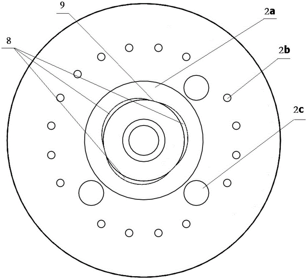
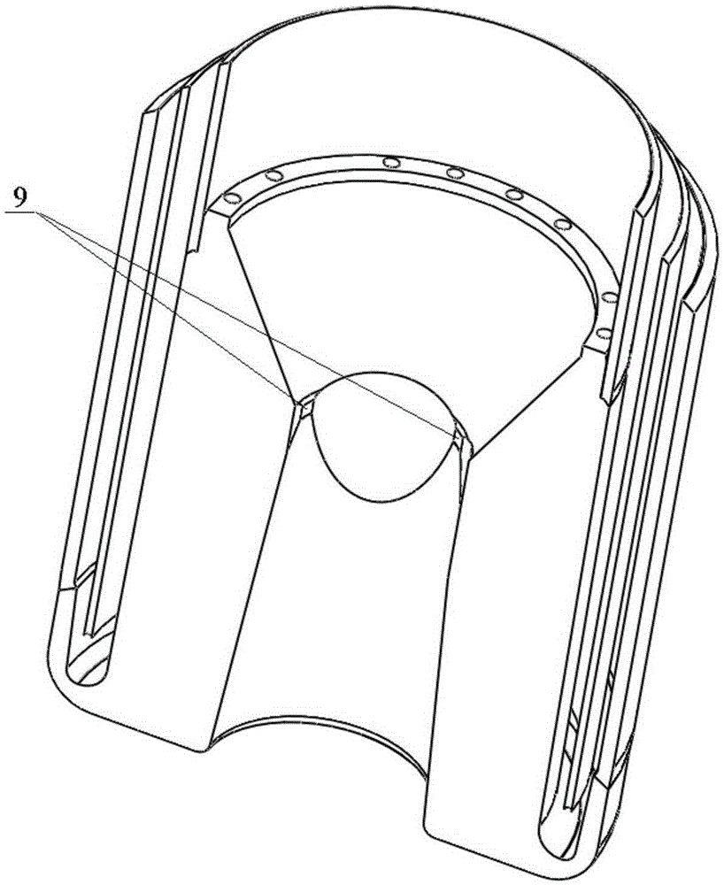
[0071] Such as Figure 5 to Figure 7 As shown, the difference between this example and Embodiment 1 is that the positioning ridge 9 as a positioning structure is arranged on the inner surface of the nozzle outer tube 2, as Figure 6 and Figure 7 As shown, there are 3 or more grooves evenly distributed along the circumference on the inner wall of the equal-diameter circular hole section; the grooves of the outer tube 2 of the nozzle and the cylindrical outer contour of the core tube 1 of the nozzle form a porous annular groove-shaped gas channel 8, The outer contour surface corresponding to the nozzle core tube 1 and the central hole 2a of the nozzle outer tube 2 is a cylindrical surface, the diameter of the cylinder of the nozzle core tube 1 is equal to the diameter of the cylinder hole of the nozzle outer tube 2, and the nozzle core tube 1 is inserted into the nozzle In the annular groove gap formed behind the central hole 2a of the outer tube 2, the total void area at the ...


PUM

PropertyMeasurementUnit
particle sizeaaaaaaaaaa

Abstract

The invention provides a high-lance-position vacuum refining method based on a coherent jet top lance. The coherent jet top lance is provided with a powder passage located at the center, a main oxygen passage located on the periphery of the powder passage and an auxiliary oxygen passage located on the periphery of the main oxygen passage; and during RH vacuum refining, oxygen enters from the main oxygen passage and the auxiliary oxygen passage to form a main oxygen flow and an auxiliary oxygen flow respectively, powder is injected into molten steel together with the main oxygen flow under the sweeping and protection of the main oxygen flow, the main oxygen flow impacts the molten steel and reacts with carbon in the molten steel to generate carbon monoxide, and carbon monoxide escaping from the molten steel is subjected to secondary combustion with the coherent surrounding accompanying auxiliary oxygen flow to heat a vacuum tank so as to reduce temperature drop of the molten steel. According to the invention, the auxiliary oxygen flow forms the surrounding accompanying flow outside the central supersonic jet flow, so that the expansion and attenuation of the central supersonic jet flow are smaller, the supersonic jet flow is longer, the penetration depth and stirring strength of the oxygen jet flow to a molten bath are increased, a lance position is raised to reduce splashing of the molten steel and slag sticking to a lance head, and the service life is prolonged.

Description

technical field [0001] The invention relates to the secondary smelting technology in the steelmaking field in the metallurgical industry, in particular to a high-lance vacuum refining method based on cluster top lances. Background technique [0002] RH vacuum refining is a iron and steel metallurgy technology developed in the 1950s. In addition to vacuum degassing, it can also decarburize by blowing oxygen and desulfurize by spraying powder, which enables large-scale smelting of ultra-low carbon clean steel. The oxygen blowing and decarburization device is first installed in the lower part of the vacuum tank, then in the middle of the vacuum tank, and finally in the top of the vacuum tank to become a water-cooled multifunctional top gun. 现有技术中,无论是RH-KTB顶枪、RH-MFB顶枪、RH-MESID顶枪、RH-PB顶枪还是中国专利申请号200420027046.4、200610076151.0、200820174977.5、200820174973.7、201110000083.0、201210346652.1、201310431081.6所涉及 The top gun or nozzle of the top gun adopts a round-hole Laval tube structure, t...

Claims


Application Information

Patent Timeline
Patent Type & Authority Applications(China)
IPC IPC(8): C21C7/10C21C7/068
Inventor 刘向东王勇杨宁川艾磊吴燕萍廖远吴令黄其明
Owner CISDI ENG CO LTD
Why Eureka
Try Eureka