Multi-station residual current test connection device

A residual current and test connection technology, which is applied in the field of multi-station residual current test and connection devices, can solve problems such as the opening clip is easy to fall off, the operation torque is large, and safety hazards are achieved, saving time, simple structure, and reducing labor costs. Effect

Inactive Publication Date: 2016-02-10
FORETECH ELEC APP JIANGSU CORP
View PDF11 Cites 3 Cited by
  • Summary
  • Abstract
  • Description
  • Claims
  • Application Information

AI Technical Summary

Problems solved by technology

However, the existing test methods are all tested by the common residual current circuit breaker tester on the market. The residual current circuit breaker tester is not equipped with a corresponding test connection device, and circuit breaker manufacturers often use open clips. The operability is not high to connect the incoming line end and the outgoing line end of the circuit breaker. The main disadvantages are the following two points;
[0004]1. Since the circuit breaker can have up to four poles, it means that 8 opening clips must be installed during the test, which is inconvenient to operate and wastes time and labor costs.
[0005]Because the products with large frames are often operated with a large torque, the vibration generated when the product is broken is relatively large, and there will be a phenomenon that the opening clip is easy to fall off, which has serious Security risks

Method used


Image

  • Multi-station residual current test connection device
  • Multi-station residual current test connection device
  • Multi-station residual current test connection device

Examples


Embodiment

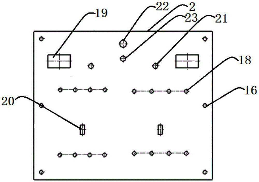
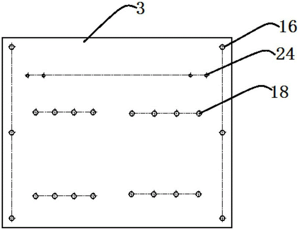
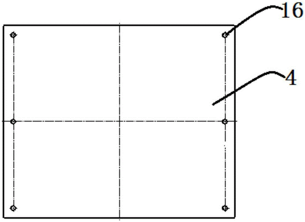
[0027] Example: refer to Figures 1 to 7 As shown, a multi-station residual current test connection device of the present invention is used in conjunction with a residual current protection circuit breaker 1 and a circuit breaker detector. 4. Six T-shaped shafts 9 passing through the panel 2, the middle panel 3, and the bottom panel 4, the toggle switch 12 provided on the panel 2, and two station assemblies, where there may be more than two station assemblies, Station components can be added as needed.

[0028] refer to Figures 5 to 7 Shown, each station assembly of the present invention all comprises the relay base 5 that is located on the middle board 3, is located at two relays 6 on the relay base 5, and 8 pass through the panel 2 and the middle board 3, and with The incoming and outgoing ports of the residual current protection circuit breaker 1 are provided with one-to-one conductive pillars 7, the micro switch 13 arranged on the panel 2 and located in the middle o...


PUM


Abstract

The invention discloses a multi-station residual current test connection device co-used with residual current protective circuit breakers and circuit breaker detectors. The connection device is characterized by comprising a faceplate, a middle plate, a bottom plate and a plurality of station components, which are arranged from top to bottom in sequence, wherein each station component comprises a relay base, relays and a plurality of electricity conducting pillars; the relay base is arranged on the middle plate; the relays are arranged on the relay base; the electricity conducting pillars pass through the faceplate and the middle plate and are arranged corresponding to inlet and outlet ports of the residual current protective circuit breakers one to one; and power lines of the circuit breaker detectors are correspondingly connected with the electricity conducting pillars by the relays one to one. The connection device has the advantages that adopting the electricity conducting pillars instead of open mouth clamps in the prior art, the connection device not only has a simple structure and strong operability and is safe and reliable but also has the effects of saving time and effectively reducing the labor cost.

Description

technical field [0001] The invention relates to a test device, in particular to a multi-station residual current test connection device. Background technique [0002] With the improvement of people's living standards and the continuous increase of household appliances, in the process of using electricity, personal electric shocks and fire accidents caused by defects in electrical equipment itself, improper use, and unfavorable safety technical measures have brought great harm to people's lives and property. Undue losses have come, and the emergence of circuit breakers with residual current protection provides reliable and effective technical means to prevent various accidents, cut off power supply in time, and protect equipment and personal safety. [0003] As a manufacturer, it is essential to test the residual current protection circuit breaker, especially for the detection of its residual current operating characteristics, each product must be tested. However, the e...

Claims


Application Information

Patent Timeline
Patent Type & Authority Applications(China)
IPC IPC(8): G01R1/04
Inventor 曹兵兵虞国荣种彪丁高峰
Owner FORETECH ELEC APP JIANGSU CORP
Why Eureka
Try Eureka