Liquid crystal display module

一种液晶显示模组、液晶显示面板的技术,应用在静态指示器、仪器、非线性光学等方向,能够解决减小驱动芯片尺寸、焊盘繁多、没有获得效益等问题,达到占用空间小、增加占用空间、减小体积的效果

Active Publication Date: 2016-02-10
WUHAN CHINA STAR OPTOELECTRONICS TECH CO LTD
View PDF5 Cites 13 Cited by
  • Summary
  • Abstract
  • Description
  • Claims
  • Application Information

AI Technical Summary

Problems solved by technology

The above scheme is intended to lead the potential on the original driver chip or the bonding pad of the flexible circuit board back to the thin film transistor array substrate by using the circuit traces on the flexible circuit board as a bridge, so that although the necessary functions can be realized, the The disadvantage is that there are many pads, and it is impossible to reduce the number of pads when the driver chip or flexible circuit board is bound, and it is impossible to reduce the area of ​​the flexible circuit board or the size of the driver chip, and the driving circuit must be bound with the help of a flexible circuit board, so that This process does not gain more benefits

Method used


Image

  • Liquid crystal display module
  • Liquid crystal display module
  • Liquid crystal display module

Examples


Embodiment Construction

[0022] The following will clearly and completely describe the technical solutions in the embodiments of the present invention with reference to the drawings in the embodiments of the present invention.

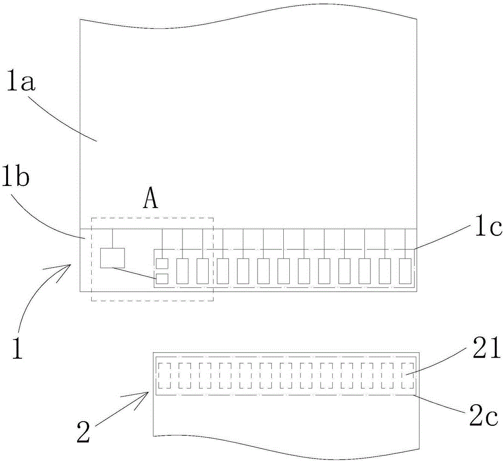
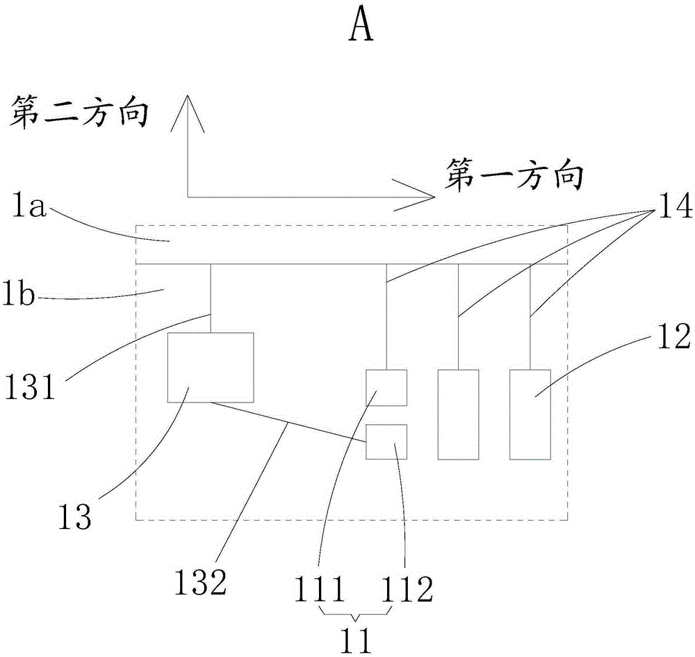
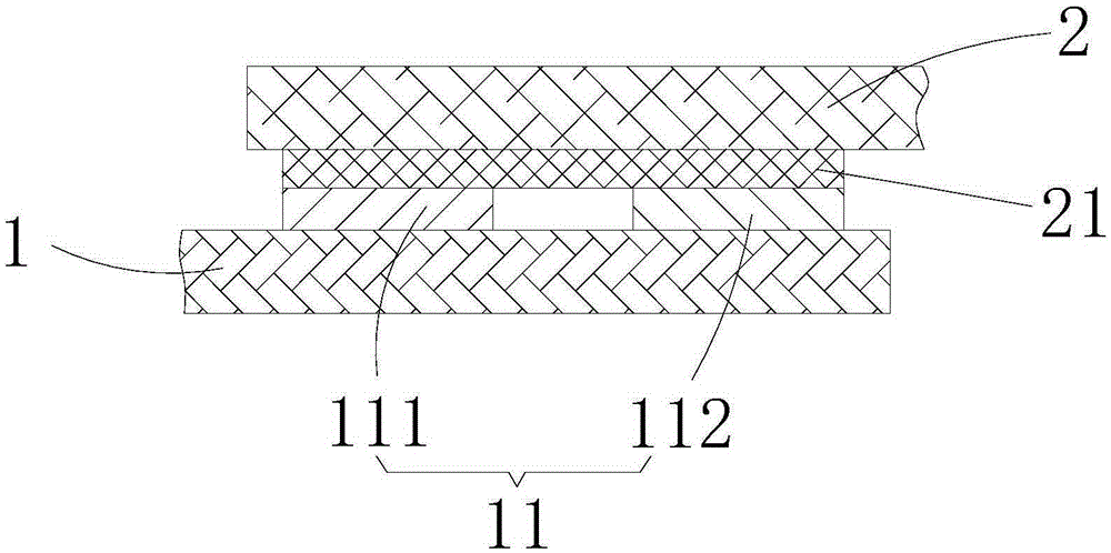
[0023] Please also refer to Figure 1 to Figure 3 , an embodiment of the present invention provides a liquid crystal display module, including a liquid crystal display panel 1 and a driving integrated circuit 2 . The liquid crystal display panel 1 includes a display area 1a and a non-display area 1b disposed around the display area 1a. The non-display area 1b is provided with a first binding area 1c and a test pad 13 . The test pad 13 is connected to the liquid crystal cell (not shown in the figure) in the display area 1a through the first test signal line 131, and the tester can electrically connect the oscilloscope to the test pad 13, thereby passing Detecting the electrical signal status of the liquid crystal cell to analyze the working state of the circuit inside the liq...


PUM


Abstract

The invention discloses a liquid crystal display module which comprises a liquid crystal display panel and a drive integrated circuit. The liquid crystal display panel comprises a testing bonding pad, a first bonding pad and a second bonding pad. The first bonding pad comprises a first sub bonding pad and a second sub bonding pad in a spaced mode. The second sub bonding pad is electrically connected with the testing bonding pad. The drive integrated circuit comprises at least two third bonding pads, the third bonding pads are bonded to the first bonding pad and the second bonding pad in a one-to-one correspondence mode, the first sub bonding pad and the second sub bonding pad are bonded to one third bonding pad together, and accordingly short-circuit between the first sub bonding pad and the second sub bonding pad is achieved. The space occupied by bonding areas of the liquid crystal display module is small.

Description

technical field [0001] The invention relates to the technical field of liquid crystal display, in particular to a liquid crystal display module. Background technique [0002] In the design and manufacture of liquid crystal display panels, when designing panel signal wiring, in addition to some basic signal lines (such as gate signal lines, data signal lines) necessary to meet the product function (normal display), the designer There will also be some other signal lines to detect whether the product performance is complete. Usually, these signal lines will be connected to the LCD panel before the LCD panel is bonded (Bonding) to the flexible circuit board (Flexible Printed Circuit, FPC) or the driver chip (DriverIC). The LCD cell test pad (Celltestpad) is used to facilitate testers to use an oscilloscope to detect its electrical signal status to analyze the working status of the circuit in the LCD Cell. In the later production, we will connect these signal circuits through th...

Claims


Application Information

Patent Timeline
Patent Type & Authority Applications(China)
IPC IPC(8): G02F1/1345
CPCG02F1/13458G02F1/1345G02F1/13452G02F1/1309G09G3/006G09G3/3648G09G2330/12
Inventor 郭星灵秦杰辉谭小平
Owner WUHAN CHINA STAR OPTOELECTRONICS TECH CO LTD
Why Eureka
Try Eureka