Capacitor shell-inserting machine

A technology of plug-in machine and capacitor, applied in the direction of capacitors, capacitor manufacturing, circuits, etc., can solve the problems of low work efficiency, no improvement in case efficiency, large core volume, etc., and achieve the effect of reducing the possibility of defective products

Inactive Publication Date: 2016-02-10
WUXI YUANCHUANG TECH CO LTD
View PDF7 Cites 11 Cited by
  • Summary
  • Abstract
  • Description
  • Claims
  • Application Information

AI Technical Summary

Problems solved by technology

[0005] However, the capacitive energy-enabling welding glue-injecting casing assembly machine in the prior art can only be applied to single-particle capacitor cores and the cores are relatively large in size, and they are still packaged one by one, so the efficiency of the casing has not been improved; The method used for the core casing is: the plastic shell is conveyed and positioned under the element, the element clamping claw is released, and the element falls into the plastic shell. During this process, the element adopts a free fall method. If there is interference from other factors, For example, if the clamping claw shakes, the falling position of the element will deviate, resulting in the failure of the casing action, and there are still technical defects
[0006] For multi-particle capacitor cores, the capacitors are usually small-sized capacitors, and the size of the element and the plastic case will also be small. At this time, the requirements for the alignment accuracy of the drop position of the element and the position of the plastic case will be very high. This device cannot It is possible to insert the multi-particle capacitors, so the multi-particle capacitors in the prior art still use manual manual insertion, which has extremely low work efficiency and high defective rate.

Method used


Image

  • Capacitor shell-inserting machine
  • Capacitor shell-inserting machine
  • Capacitor shell-inserting machine

Examples


Embodiment Construction

[0074] The present invention will be described in further detail below in conjunction with the accompanying drawings.

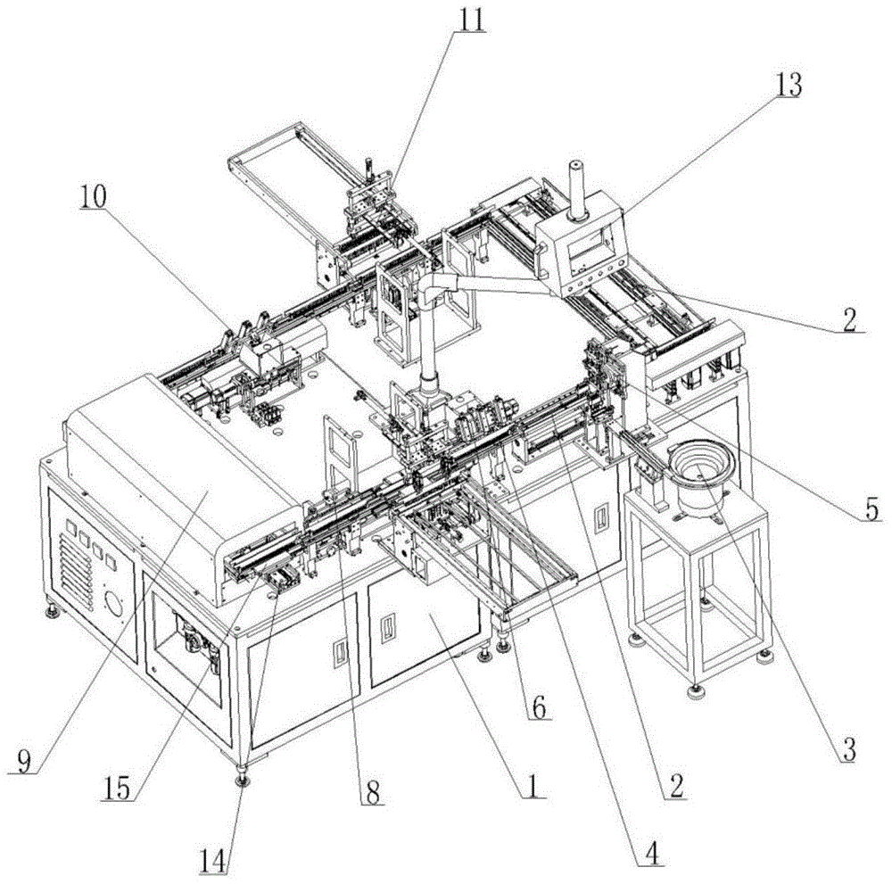
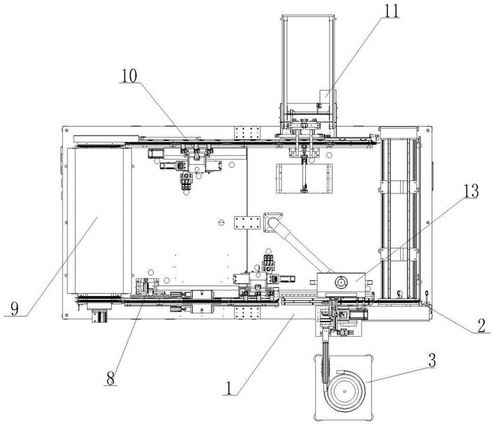
[0075] A capacitor inserting machine, characterized in that it includes a body 1, a guide rail 2, a vibrating feeding tray 3, a carrier 4 provided with a groove, and can transport the casing at the outlet of the vibrating feeding tray 3 to the carrier 4 The first transfer arm 5 on the top, a plurality of first dispensers 6, a limit device 7 for limiting the distance and position when the multi-particle capacitor falls into the carrier 4, and a pressing device 8 for pressing the capacitor and the casing , a drying device 9, a plurality of second dispensing machines 10, a jacking device 11 that ejects the case in the carrier 4, a second transfer arm 12 that removes the capacitor that has been cased and a center console 13. The guide rail 2 is installed on the machine body 1, the carrier 4 is located in the guide rail 2 and is slidably matched with the guide rai...


PUM


Abstract

The invention relates to the field of capacitor production processes, in particular to a capacitor shell-inserting machine which is capable of performing mechanical automatic shell-inserting package on a plurality of granular capacitors without the need for a manual operation and is extremely low in defective rate. The capacitor shell-inserting machine comprises a machine body, a guide rail, a vibratory feed plate, a carrier with a groove, a first conveying arm capable of conveying sleeving shells at a discharge hole of the vibratory feed plate onto the carrier, a plurality of first dispensing machines, a limiting apparatus used for limiting the spacings and positions of the granular capacitors when falling into the carrier, a pressing apparatus used for pressing the capacitors and the sleeving shells, a drying apparatus, a plurality of second dispensing machines, a second conveying arm used for removing the capacitors sleeved with the shells, and a center console, wherein the guide rail is mounted on the machine body; the carrier is positioned in the guide rail and is in sliding fit with the guide rail; and the first conveying arm, the first dispensing machines, the limiting apparatus, the pressing apparatus, the drying apparatus, the second dispensing machines and the second conveying arm are mounted on the machine body in sequence.

Description

technical field [0001] The invention relates to the field of capacitor production technology, in particular to a capacitor case inserting machine. Background technique [0002] In the traditional capacitor production process, the assembly of the capacitor core and the plastic case is generally done by manual casing, that is, the operator works manually to cover the capacitor core with the plastic case one by one. This operation is not only time-consuming and laborious, but also expensive. It will lead to bad situations such as skewing of the casing and incomplete insertion of the core into the casing. [0003] In order to solve the above technical problems, some equipment that adopts mechanical automatic casing has appeared in the prior art. The invention patent of Chinese Patent Publication No. 203444991 discloses a capacitor-enabled welding glue injection casing assembly machine. In its specification, The process of setting the plastic case for the capacitor core is as fo...

Claims


Application Information

Patent Timeline
Patent Type & Authority Applications(China)
IPC IPC(8): H01G13/00
Inventor 杨旭包科达
Owner WUXI YUANCHUANG TECH CO LTD
Why Eureka
Try Eureka