Secondary ripple current suppression method for direct current micro-grid two-way energy storage converters

A DC micro-grid and secondary ripple technology, which is applied in the direction of electrical components, output power conversion devices, etc., can solve the problems of not considering the influence of line impedance output power, etc., to improve the effect of parallel current sharing, enhance the suppression effect, The effect of reducing bias

Active Publication Date: 2016-02-10
HUNAN UNIV
View PDF6 Cites 15 Cited by
  • Summary
  • Abstract
  • Description
  • Claims
  • Application Information

AI Technical Summary

Problems solved by technology

However, the above two methods do not consider the influence of line impedance on output power

Method used


Image

  • Secondary ripple current suppression method for direct current micro-grid two-way energy storage converters
  • Secondary ripple current suppression method for direct current micro-grid two-way energy storage converters
  • Secondary ripple current suppression method for direct current micro-grid two-way energy storage converters

Examples


Embodiment Construction

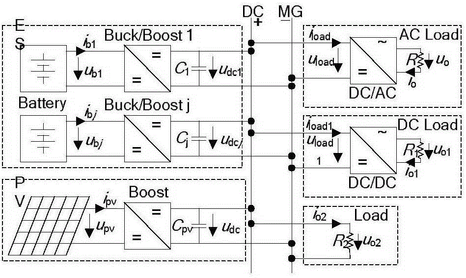
[0028] figure 1 Shown is a DC microgrid structure, mainly composed of photovoltaic (photovoltaic, PV) modules, energy storage (energystorage, ES) modules and loads. Photovoltaic modules use Boost converters; energy storage modules use energy storage converters, namely Buck / Boost converters, to achieve bidirectional energy flow; DC / AC converters use three-phase bridge circuits to avoid control and Stability issues, loads are simulated by DC / AC and DC / DC converters and resistive loads. Among them, j=1, 2, ..., n, u b1 , u bj and i b1 i bj are battery side voltage and current respectively, u pv and i pv are the photovoltaic side voltage and current, respectively, u dc1 , u dcj and u dc are the DC side capacitance C of the energy storage converter 1 、C j and C pv The voltage across the terminals, u load , u load1 and i load i load1 Respectively, DC / AC and DC / DC converters are connected to resistive loads R and R 1 When the DC side voltage and current, u o , u o1...


PUM


Abstract

The invention discloses a secondary ripple current suppression method for direct current micro-grid two-way energy storage converters. The secondary ripple current suppression method mainly comprises three parts, namely a droop control, an outer loop PI control of introducing a capacitor voltage fed back by a band-pass filter and an inner loop P control of introducing an inductive current fed back by the band-pass filter, wherein the droop control obtains a direct current side reference voltage of an outer voltage loop; the outer voltage loop introduces the capacitor voltage feedback of the band-pass filter to enhance the secondary ripple suppression effect; and an inner current loop introduces the inductive current feedback of the band-pass filter to solve the problem of a low dynamic response speed caused by limitation on the cutoff frequency of the voltage of the outer loop in the conventional voltage and current double closed-loop control. According to the secondary ripple current suppression method, the deviation of output voltages between the energy storage converters is reduced; the parallel current equalizing effect is improved; the service lifetime of a power electronic device is prolonged; and the current stress and the conduction losses of a switching tube are reduced.

Description

technical field [0001] The invention relates to the fields of new energy distributed power generation and DC microgrids, in particular to a secondary ripple current suppression method for a DC microgrid bidirectional energy storage converter. Background technique [0002] With the increasingly serious energy crisis and environmental pollution, new energy distributed power generation technology has received extensive attention and research, and microgrids have also emerged as the times require. Compared with the AC microgrid, the DC microgrid system has the advantages of simple structure, less energy conversion times, no need to consider frequency, phase and reactive power compensation equipment, and high power supply quality, which promotes the rapid development of DC microgrid. [0003] A DC microgrid is a system composed of distributed power generation, energy storage devices, energy conversion devices, and loads. It can be operated in parallel with the large power grid or...

Claims


Application Information

Patent Timeline
Patent Type & Authority Applications(China)
IPC IPC(8): H02M1/14
Inventor 陈燕东杨苓罗安周小平周乐明陈智勇伍文华怀坤山王自力
Owner HUNAN UNIV
Why Eureka
Try Eureka