A duplexing filter circuit and an implementation method

A technology of duplex filter and realization method, which is applied in the direction of electrical components, impedance network, multi-terminal pair network, etc., can solve problems such as complex circuit, large structure, and difficult design, and achieve simple realization method, small circuit size, and design convenient effect

Inactive Publication Date: 2016-02-10
TOEC TECH
View PDF3 Cites 2 Cited by
  • Summary
  • Abstract
  • Description
  • Claims
  • Application Information

AI Technical Summary

Problems solved by technology

The existing duplexer cavity filter generally has a large structure and high cost. Once the circuit parameter requirements change, it needs to be re-tuned, and there are deficiencies in versatility.
There is also a duplexer composed of two bandpass LC filters. The disadvantage is that the circuit is more complicated and the design is more difficult.

Method used


Image

  • A duplexing filter circuit and an implementation method
  • A duplexing filter circuit and an implementation method

Examples


Embodiment Construction

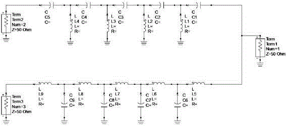
[0011] Such as figure 1 As shown, a duplex filter circuit consists of Term1 port, Term2 port, Term3 port and high-frequency capacitors C1, C2, C3, C4, C5, C6, C7, C8, C9 and high-frequency inductors L1, L2, L3 , L4, L5, L6, L7, L8, L9.

[0012] The circuit connection is that one end of the Term2 port is connected to one end of the Term3 port through high-frequency capacitors C5, C4, C3, C2, C1, high-frequency inductors L5, L6, L7, L8, and L9, and the other ends of the Term2 port and Term3 port are respectively Grounding, the connection ends of high-frequency capacitor C1 and high-frequency inductor L5 are grounded through Term1 port, the connection ends of high-frequency capacitors C5 and C4 are grounded through high-frequency inductor L4, and the connection ends of high-frequency capacitors C4 and C3 are grounded through high-frequency inductor L3 , the connecting ends of high-frequency capacitors C3 and C2 are grounded through high-frequency inductor L2, the connecting ends...


PUM


Abstract

The invention provides a duplexing filter circuit and an implementation method. A filter circuit between a Term 1 port and a Term 2 port is a reciprocal network, and the Term 1 port serves as an input port while the term 2 port serves as an output port and vice versa. A radio frequency signal RF1 is input from the Term 2 port and is output from the Term 1 port via high frequency capacitors; or the radio frequency signal RF1 is input from the Term 1 port and is output from the Term 2 port via the high frequency capacitors. A filter circuit between the Term 1 port and a Term 3 port is a reciprocal network, and the Term 1 port serves as an input port while the term 3 port serves as an output port and vice versa. A frequency signal RF2 is input from the Term 3 port and is output from the Term 1 port via high frequency inductors; or the frequency signal RF2 is input from the Term 1 port and is output from the Term 3 port via the high frequency inductors. For high frequency circuits within the short-wave and ultrashort-wave frequency range, two paths of radio frequency signals with different frequencies can be isolated from each other and share transmitting and receiving antennas; if the power of any one path of radio frequency signals is attenuated by more than 60dB in the frequency range of the other path of radio frequency signals, the isolation between the two paths of radio frequency signals exceeds 60dB.

Description

technical field [0001] The circuit of the invention relates to a duplex filter circuit and a realization method for two-way radio frequency signals to be isolated from each other and share a receiving and transmitting antenna. Background technique [0002] In general, a radio frequency filter has two ports, one for signal input and the other for signal output, and the impedances of both ports are matched at 50 ohms. When it is necessary to connect a high-pass filter and a low-pass filter together in parallel to form a duplex filter for isolating two RF signals from each other and sharing a transceiver antenna, the common port of the two parallel filters cannot be directly connected to the together, and can only be connected together after proper impedance matching. When the power of the radio frequency signal is very large, a cavity resonator can be used to make a duplex filter. When the radio frequency signal is relatively small, a filter circuit can be built with discrete...

Claims


Application Information

Patent Timeline
Patent Type & Authority Applications(China)
IPC IPC(8): H03H7/01
Inventor 刘堃宋光伟苗尧飞
Owner TOEC TECH
Why Eureka
Try Eureka