Electric fan and electric vacuum cleaner

A blower, electric technology, applied in the manufacture of motor generators, electric components, machines/engines, etc., can solve the problems of difficult winding orderly arrangement, long winding length, hindering the efficiency improvement and light weight of electric blowers, etc., to achieve easy orderly arrangement. , the effect of improving efficiency

Inactive Publication Date: 2016-02-10
MITSUBISHI ELECTRIC CORP +1
View PDF6 Cites 0 Cited by
  • Summary
  • Abstract
  • Description
  • Claims
  • Application Information

AI Technical Summary

Problems solved by technology

As a result, the arrangement of the windings can only be left to itself, it is difficult to arrange the windings neatly (arrange the windings in a regular and high-density manner) and the winding space factor (the actual winding of the winding relative to the space prepared for the arrangement of the winding ratio) is low, and in addition, the winding length is long, so it hinders the efficiency improvement and weight reduction of the electric blower

Method used


Image

  • Electric fan and electric vacuum cleaner
  • Electric fan and electric vacuum cleaner
  • Electric fan and electric vacuum cleaner

Examples


Embodiment approach 1

[0076] structure

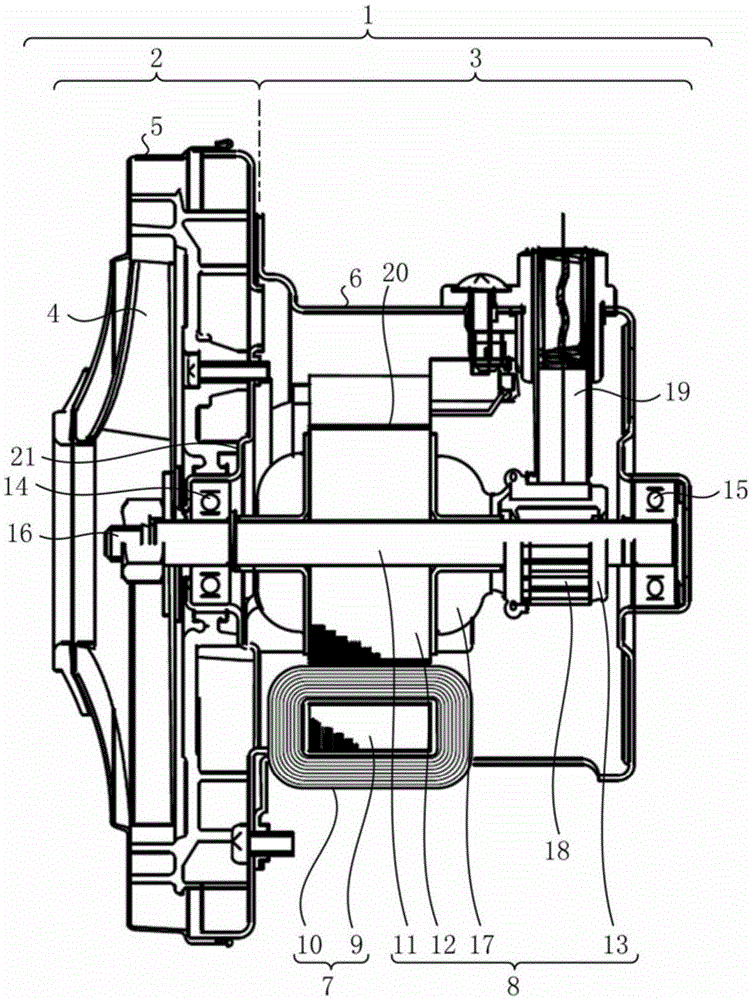
[0077] figure 1It is a vertical cross-sectional view showing a schematic structure of the inside of the electric blower according to the present embodiment. The electric blower 1 is roughly divided into two units, a blower unit 2 that generates suction force, and a commutator motor 3 that drives the blower unit 2 . Electric blower 1 can be applied to, for example, an electric vacuum cleaner.

[0078] The air blower 2 includes: a fan 4 having a plurality of blades; and a fan guide 5 that covers the fan 4 and guides the air that circulates with the rotation of the fan 4 to the inside of the commutator motor 3 . The circulating air cools the commutator motor 3 that generates heat during operation, and is discharged from an opening (not shown) provided in the frame 6 .

[0079] Commutator motor 3 includes: stator 7, which is fixed on the inner side of cup (tube)-shaped frame 6, and plays the role of excitation; The way is supported, play the role of the arma...

Embodiment approach 2

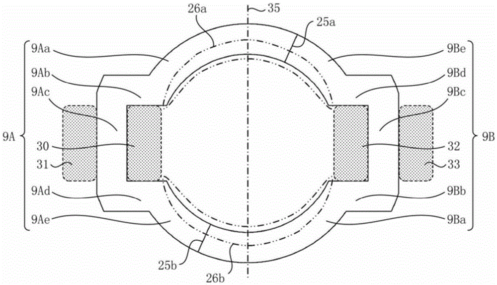
[0097] In this embodiment, regarding the shapes of the two C-shaped portions 9A and 9B constituting the stator core 9 , portions different from those in Embodiment 1 will be described.

[0098] structure

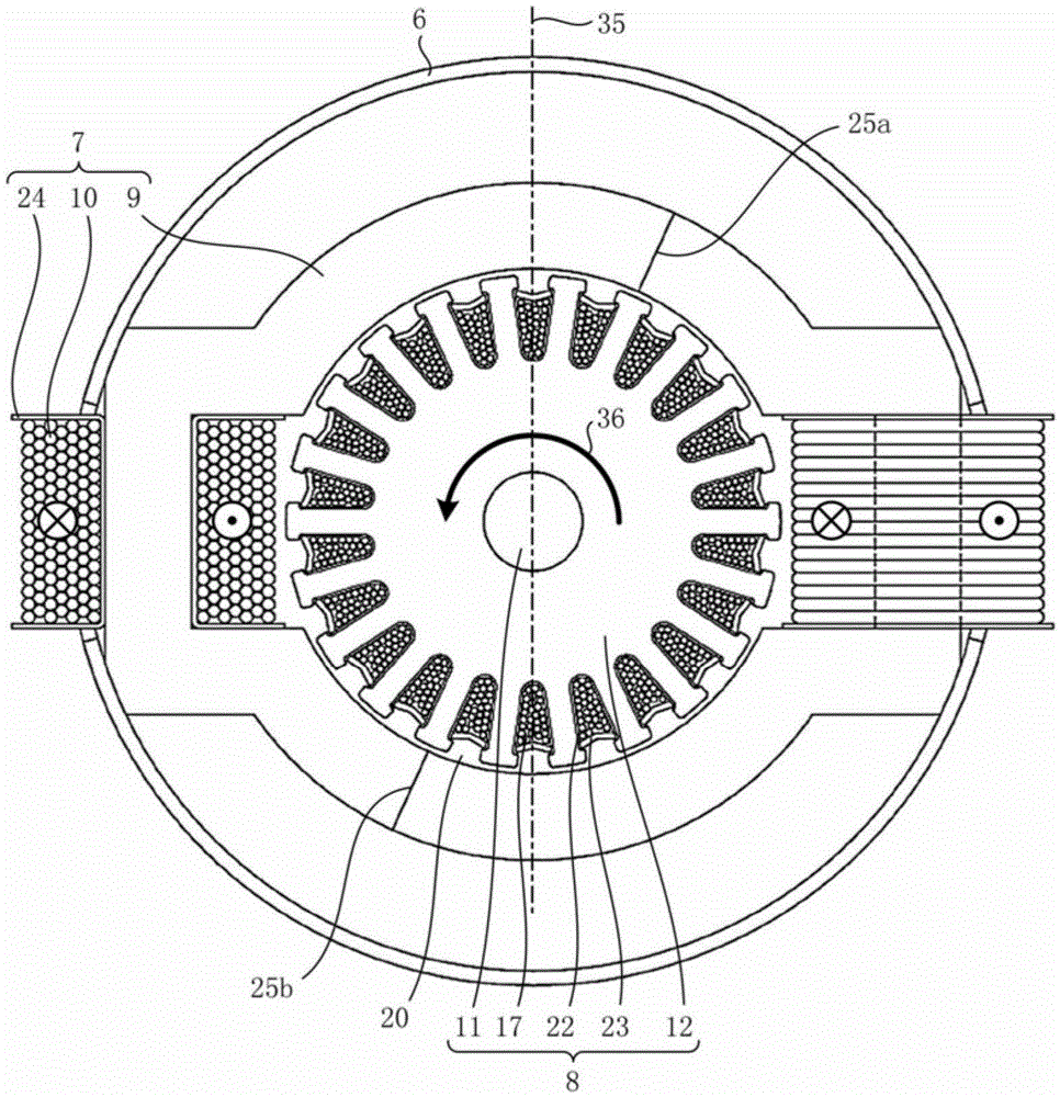
[0099] In the electric blower 1, if the radial widths (magnetic path widths) of the left end portion 9Aa, the right end portion 9Be, the right end portion 9Ae, and the left end portion 9Ba of the two C-shaped portions 9A, 9B facing the rotor 8 are closer to the iron The smaller the core division positions 25a and 25b, the better. Figure 6 and Figure 7 An example application is shown in . Figure 6 and Figure 7 and image 3 Similarly, it is a figure which looked at the stator core 9 from an axial direction, and is a figure which shows the shape of the stator core 9 of this embodiment. exist Figure 6 Among them, the surfaces where the C-shaped portion 9A and the C-shaped portion 9B abut are provided with a small width at the core division positions 25a and 25b. In a...

Embodiment approach 3

[0107] In the present embodiment, the differences from Embodiments 1 and 2 will be described regarding the winding method of the field coil 10 .

[0108] structure

[0109] In the electric blower 1, the field windings 10 are arranged in a triangular arrangement in the spaces 30 and 32 inside the stator core 9. (The spaces 31 and 33 outside the stator core 9 or the coil ends on the upper and lower sides in the axial direction) are more preferable.

[0110] effect

[0111] By setting the winding state of the field winding 10 as described above, the outer shape of the stator core 9 (specifically, the lengths of the shoulders 9Ab, 9Ad, 9Bb, and 9Bd) can be reduced to improve efficiency and reduce weight. Next, the reason will be described in more detail.

[0112] The cross-sectional area of ​​the space 30, 32 is approximately the product of the length of the arm portion (9Ac, 9Bc) and the length of the shoulder portion (9Ab, 9Ad, 9Bb, 9Bd). Since the length of the arms (9Ac, 9...


PUM


Abstract

Provided is an electric fan, comprising a stator provided with a stator core and a field winding and a rotor disposed on the inner side of the stator, wherein: the stator core is divided into two C-shaped sections (9A, 9B) at two core division positions (25a, 25b) offset from a magnetic pole axis in the reverse of the direction of rotation; the C-shaped sections (9A, 9B) are shaped so that a core portion in a position in a direction perpendicular to the magnetic pole axis (35) is shaped so as to bulge outward in a straight U shape at three straight sections; a region for winding the field winding is created using spaces formed between the outwardly bulging U shape and the outer periphery of the rotor, and spaces formed in positions that are symmetrical to the former spaces and sandwich arm sections (9Ac, 9Bc) of the straight sections in the center; and the radial widths of the portions that face the rotor become smaller as they draw closer to the core division positions (25a, 25b).

Description

technical field [0001] The invention relates to an electric blower and an electric vacuum cleaner. Background technique [0002] An electric blower in which a blower unit and a motor are integrated, mounted in an electric vacuum cleaner or the like, is generally used at a high rotational speed of 30,000 to 45,000 r / min. Therefore, an electric blower uses a commutator motor including a stator having two magnetic poles and a field winding, and a rotor located inside the stator and having an armature winding and a commutator. [0003] In conventional electric blowers, the magnetic poles protrude inward from the yoke having a roughly square shape, and the magnetic pole angle (the angle formed by two straight lines connecting the two ends of the arc at the front end of the magnetic pole to the center of the shaft) is 120° to 140° °. The field winding is wound around the magnetic pole, and when the coil ends passing between the left and right sides of the magnetic pole are conne...

Claims


Application Information

Patent Timeline
Patent Type & Authority Applications(China)
IPC IPC(8): F04D29/00F04B39/00H02K1/14
CPCH02K15/095F04D25/0606H02K1/141H02K23/02H02K23/40
Inventor 桶谷直弘马场和彦早津守安岛武彦尾高秀一滨崎光将
Owner MITSUBISHI ELECTRIC CORP
Why Eureka
Try Eureka