
Control method for continuous rolling of wire rods and bars

A control method, rod and wire technology, applied in metal rolling, tension/pressure control, etc., can solve the problems of small cross-sectional size of rolled pieces, low efficiency of tension adjustment, and long debugging process, so as to reduce product waste , Release the workload and improve the operation rate

Active Publication Date: 2016-02-17
SGIS SONGSHAN CO LTD
View PDF4 Cites 4 Cited by
  • Summary
  • Abstract
  • Description
  • Claims
  • Application Information

AI Technical Summary

Problems solved by technology

[0033] In the existing control method, the control system only adjusts the tension once when rolling a rolling piece, and the efficiency of tension adjustment is very low
At the same time, in order to ensure the stability of the rolling process after adjustment, the speed adjustment (△v) of the rolling piece tension control must be controlled within a small range. Generally, the limit is within ±0.5% of the reference speed, and only small, slow The speed of adjustment seriously limits the adjustment effect
[0034] In actual production, tension adjustment often needs to roll multiple billets (generally 4 to 5 billets) to adjust the tension of the rolled piece to the set range. The cross-sectional size of the rolled piece is pulled down, which seriously affects the quality of the product and is very easy. generate a lot of waste
The debugging process takes a long time, which seriously affects the production rhythm and reduces the production efficiency

Method used


Image

  • Control method for continuous rolling of wire rods and bars
  • Control method for continuous rolling of wire rods and bars
  • Control method for continuous rolling of wire rods and bars

Examples


Embodiment 1

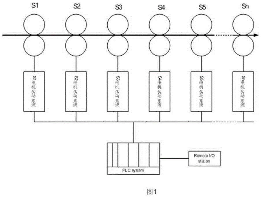
[0067] Such as figure 1 , figure 2 and Figure 4 Shown, S i is the continuous rolling stand number, i is 1, 2, 3, 4, ..., n, 21, 22, 23, 24, 25, 26 are frequency conversion devices, 30 is the communication network, 40 is the PLC control system, 41 is the remote I / O Substation. The exchange of data (such as speed, rolling torque, etc.) between the PLC control system 40 and the frequency conversion devices 21 , 22 , 23 , 24 , 25 , 26 is transmitted through the communication network 30 .

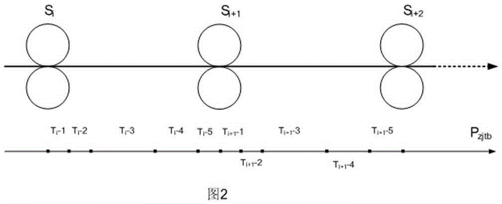
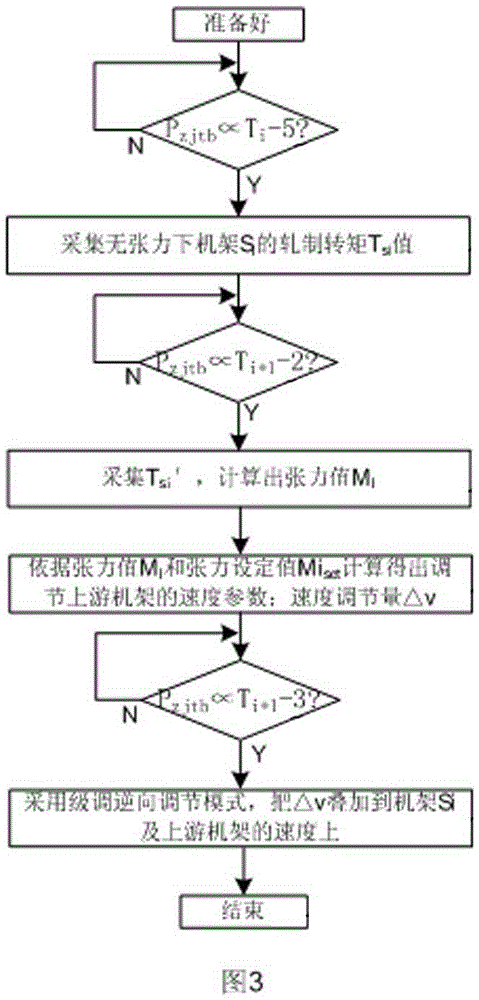
[0068] T i -1,T i -2,T i -3,T i -4,T i -5, is the head P of the rolled piece zjtb This time period is automatically calculated by the control system via the time segment of the area. where T i+1 -1 time period for mill S i+1 Bite steel stage, T i+1 -2 time period for the rolled piece biting into the stand S i+1 after mill s i Rolling torque sampling, tension and adjustment calculation stage, T i -3 is the tension adjustment stage, T i+1 -4 is the rolling mill speed recovery s...


PUM


Abstract

The invention relates to a control method for continuous rolling of wire rods and bars. The control method comprises the following control steps: firstly, calculating a rolling torque Tsi value of a frame Si without tension; secondly, acquiring an initial speed Vi+1 of a frame Si+1 when the head Pzjtb of a rolled piece is at a stage Ti+1-2; thirdly, calculating a speed regulation amount delta v according to a formula 4; fourthly, independently adjusting the speed of the frame Si+1; fifthly, independently adjusting the speed of the frame Si+1 in a single frame regulation mode; sixthly, judging whether a tensioned value of the rolled piece after the speed is regulated meets a set requirement: when the head Pzitb of the rolled piece is located at a stage Ti+1-4, restoring the speed Vi+1' of the frame Si+1 to the initial speed value Vi+1 of the frame Si+1 in a reverse step regulation mode, so that the speeds of the frame Si+1 and an upstream frame thereof are kept matched with a speed of a downstream frame Si+2; and finally, finishing tension regulation of this time. The production efficiency is improved, and the labor intensity of the operating personnel is reduced; the product quality is improved, and product wastes generated at a debugging stage are greatly reduced; a remarkable technical effect is achieved, and obvious economic benefit and social benefit also are achieved.

Description

technical field [0001] The invention belongs to the technical field of electrical automation control, and relates to a continuous rolling control method for rods and wires for adjusting the tension of rolled pieces between rolling mills. Background technique [0002] In the continuous rolling production line, especially in the bar and wire continuous rolling production line, the ideal stable rolling state is the second flow rate of the rolled piece passing through two adjacent stands (second flow rate=V 1 ×S 1 =V 2 ×S 2 =V i ×S i , where V i is the rolling speed of stand i, S i is the cross-sectional area of ​​the rolled piece of the stand i, i is 1, 2, 3, ..., n, the same below) are equal. In the actual production process, the speed mismatch between adjacent racks is the main reason for the unequal second traffic between racks. [0003] The formation of rolling stock tension is caused by the difference in second flow rate between two adjacent stands. If the second ...

Claims


Application Information

Patent Timeline
IPC IPC(8): B21B37/48
CPCB21B37/48B21B2265/06
Inventor 胡占民房继昀彭科梁志宏
Owner SGIS SONGSHAN CO LTD
Learn More