Fiber laser welding method for liquid crystal display bracket

A liquid crystal display, fiber laser technology, applied in laser welding equipment, welding equipment, welding equipment and other directions, can solve the problems of molten pool metal pollution, easy welding penetration of bracket corners, large heat affected zone, etc., to improve enterprise production efficiency, The effect of reducing production cost and ensuring welding quality

Active Publication Date: 2016-10-26
YANGJIANG KNIFESCISSOR HARDWARE RES INSTITUTION OF IND TECH
View PDF6 Cites 0 Cited by
  • Summary
  • Abstract
  • Description
  • Claims
  • Application Information

AI Technical Summary

Problems solved by technology

[0003] The traditional welding method of liquid crystal display bracket is TIG welding, which has low efficiency, large heat-affected zone, large welding thermal deformation, and the corner of the bracket is easy to weld through, and the defective rate is high. In addition, when TIG welding, the tungsten rod will melt Pollution of pooled metals so that welded products cannot be exported

Method used


Image

  • Fiber laser welding method for liquid crystal display bracket
  • Fiber laser welding method for liquid crystal display bracket

Examples


Embodiment Construction

[0024] The present invention will be described in further detail below in conjunction with the accompanying drawings.

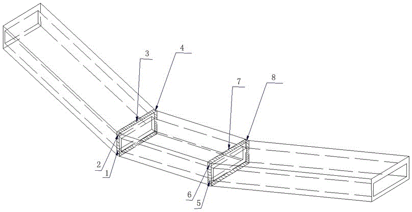
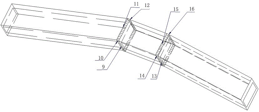
[0025] Such as figure 1 As shown, the bracket is composed of three sections of square tubes, the material of which is preferably Q195 carbon structural steel, and the thickness of the tube wall is more than 1.5mm. The blanking of the square tubes is formed by wire cutting. The gap at the center is less than 0.3mm, three sections of square tubes are butted, the middle section of short square tube is placed horizontally, and the other two sections of long square tubes are inclined at 10° and symmetrically distributed on both sides of the short square tube. Before welding, it is best to clean the oil at 50mm around the weld with alcohol, which can reduce its reflection on the laser, increase the light absorption rate of the workpiece, and increase the penetration depth to ensure welding quality.

[0026] In this embodiment, the IPG YLS-1000 fiber laser is used ...


PUM

PropertyMeasurementUnit
thicknessaaaaaaaaaa

Abstract

The invention relates to a welding forming method of a liquid crystal display support, in particular to a method for welding the liquid crystal display support by means of advanced optical fiber laser. The method comprises the following steps that three sections of square tubes forming the support are placed on an automatic clamp and are in butt joint; and an optical fiber laser welding head is adjusted to reach the preset position, welding of a weld joint on the front face of the support is performed at first, the automatic clamp is driven to rotate by 180 degrees after welding is completed, and then welding of a weld joint on the back face of the support is performed. According to the technological parameters, optical fiber laser is continuous wave, the wavelength is 1064 nm, the laser power needed when a vertical weld joint and a flat weld joint are welded is 500-1000 W, the welding speed is 15-25 mm s<-1>, the laser power needed when a fillet weld joint is welded is 500-900 W, and the welding speed is 15-25 mm s<-1>. The method has the beneficial effects that compared with traditional welding methods, the laser welding defective rate of the liquid crystal display support is quite low, the automatic laser welding quantity production of the display support is achieved, the welding quality is ensured, the enterprise production efficiency is improved, and meanwhile the production cost of a single workpiece is lowered.

Description

technical field [0001] The invention relates to a welding forming method for a liquid crystal display support, in particular to a method for welding a liquid crystal display support using an advanced optical fiber laser. Background technique [0002] The LCD monitor stand can help solve various technical problems that people encounter when operating computers at home or in industrial and commercial offices. It adopts ergonomic design, which can prevent health problems caused by work fatigue, improve work efficiency, and bring life and harmony. The ideal space for work has been widely used in retail, entertainment, finance, medical care, transportation and other fields, and its products cover single-screen, dual-screen, large-format splicing screens and other categories. [0003] The traditional welding method of liquid crystal display bracket is TIG welding, which has low efficiency, large heat-affected zone, large welding thermal deformation, and the corner of the bracket i...

Claims


Application Information

Patent Timeline
Patent Type & Authority Patents(China)
IPC IPC(8): B23K26/24B23K26/14B23K26/08B23K26/60B23K26/70B23K37/04
CPCB23K26/0823B23K26/14B23K26/24B23K37/0443B23K2101/24
Inventor 张瑞华屈岳波尹燕刘一民吴岸伟裴向东
Owner YANGJIANG KNIFESCISSOR HARDWARE RES INSTITUTION OF IND TECH
Why Eureka
Try Eureka