Automatic shot blasting device for large steel tube or steel beam

A technology of shot blasting device and steel pipe, which is applied in the direction of abrasive feeding device, used abrasive processing device, abrasive, etc., which can solve the problem of unfavorable health of environmental operators, failure to meet standards and product quality requirements, shot blasting Problems such as poor uniformity of roughness value, etc., achieve the effect of improving production safety, low cost, and large internal space

Inactive Publication Date: 2016-02-17
ANHUI JIXI JIADE STEEL STRUCTURE
View PDF7 Cites 4 Cited by
  • Summary
  • Abstract
  • Description
  • Claims
  • Application Information

AI Technical Summary

Problems solved by technology

[0003] The original conventional steel pipe and steel beam shot blasting device usually has less steel structure and less internal space, and the shot blasting box is easily damaged. It is not suitable for processing large steel pipes and steel beams, and the steel pipes and steel beams cannot be rotated. The uniformity is not good enough to meet the standards and product quality requirements
At the same time, during the operation of the traditional shot blasting machine, the high-speed impact of steel sand and steel shot will generate a lot of dust, which seriously affects the working environment and is extremely harmful to the environment and the health of the operators.
In addition, in the production process, the recycling of steel grit is completely dependent on manual work, which not only increases labor intensity, but also has a low recycling rate, and the increase in production costs caused by the loss of steel grit has also become a problem that enterprises cannot ignore

Method used


Image

  • Automatic shot blasting device for large steel tube or steel beam
  • Automatic shot blasting device for large steel tube or steel beam
  • Automatic shot blasting device for large steel tube or steel beam

Examples


Embodiment 1

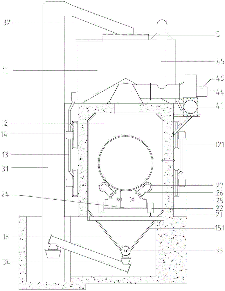
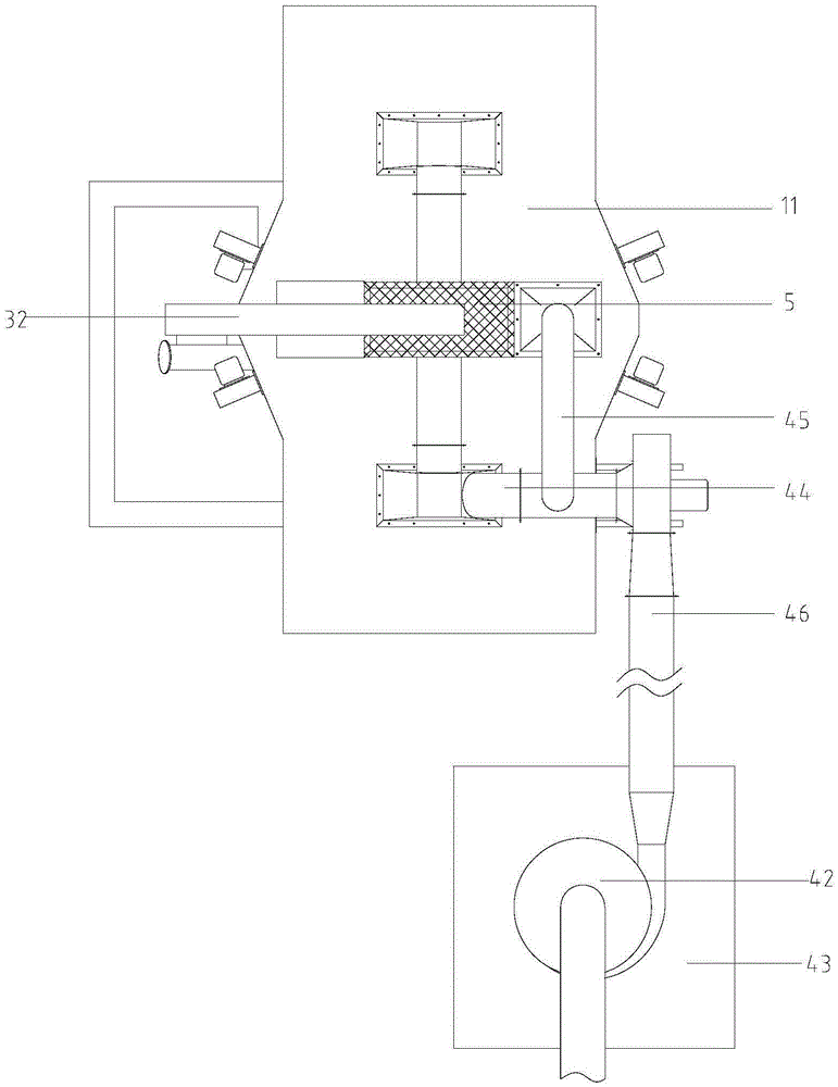
[0028] This embodiment has provided a kind of large-scale steel pipe steel girder automatic shot blasting device, has such as Figure 1-5 The structure shown includes shot blasting chamber, workpiece pushing vehicle system, circulating sand blasting system, and purification system.

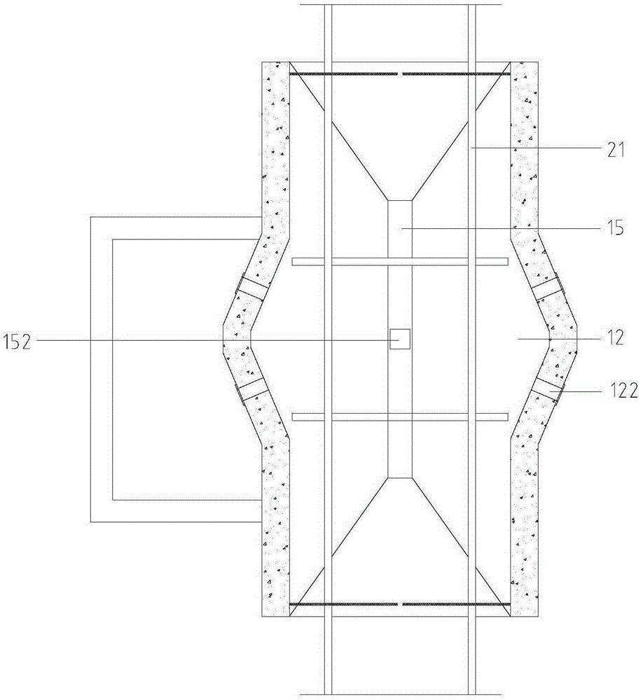
[0029] The shot blasting chamber includes a sand storage box 11, a sand blasting chamber 12, a sand delivery pipe 13 and a shot blasting head 14, wherein:

[0030] The whole of the sand storage box 11 is an inverted M shape, and its size is 500-800mm wide, 2500-3000mm long, and 1500-2000mm high. The wall thickness is 4-8mm, and the slope at the bottom is inclined at an upward angle of 30°-60° so that the steel grit slides to both sides; The hole reserved on the side is installed with the electromagnetic dispensing valve as described below;

[0031] The sandblasting chamber 12 is cast from reinforced concrete, with a cross-section width of 1.5-2.0m, a height of 2.5-3.0m, a length of 3.5-4.5m, and...


PUM

PropertyMeasurementUnit
Thicknessaaaaaaaaaa
Thicknessaaaaaaaaaa

Abstract

The invention discloses an automatic shot blasting device for a large steel tube or steel beam. The automatic shot blasting device comprises a shot blasting chamber, a workpiece pushing car system, a circulating sand blasting system and a purification system, wherein the shot blasting chamber comprises a sand blasting chamber which is provided with a channel allowing a workpiece to pass through; the workpiece pushing car system is arranged along the workpiece channel of the sand blasting chamber; the circulating sand blasting system comprises an auger conveying component, a steel shot hoister and a sand-sliding pipe; the purification system comprises an air pipe, a fan, a cyclone separator and a dust removing chamber. The inner space of the sand blasting chamber of the automatic shot blasting device is large and particularly suitable for surface treatment for the large steel tube or steel beam. The automatic shot blasting device can prevent dust from polluting the environment, greatly reduce steel shot loss and relieve labor intensity and has the advantages of being small in pollution, low in cost and capable of improving production safety. The workpiece pushing car system drives the workpiece to automatically rotate, uniform effects on all the surfaces of the workpiece are guaranteed, nonuniformity of roughness values is reduced, and the product quality is guaranteed.

Description

technical field [0001] The invention relates to the field of steel processing equipment, in particular to an automatic shot blasting device for large steel pipe steel girders. Background technique [0002] At present, shot blasting machines are commonly used to clean and derust the surface of large steel pipes, steel beams and other workpieces. The working principle of the shot blasting machine is to drop steel sand and steel shots at high speed and impact on the surface of the workpiece through the shot blaster to remove pollutants, burrs, rust, etc. on the surface of the workpiece. Compared with other surface treatment technologies, it can strengthen the surface performance of the workpiece , which has the advantage of being faster and more efficient. [0003] The original conventional steel pipe and steel beam shot blasting device usually has less steel structure and less internal space, and the shot blasting box is easily damaged. It is not suitable for processing large...

Claims


Application Information

Patent Timeline
IPC IPC(8): B24C3/14B24C3/08B24C7/00B24C9/00
CPCB24C3/14B24C3/083B24C7/0092B24C9/00B24C9/003
Inventor 许家德汪鹏程高跃辉方正成
Owner ANHUI JIXI JIADE STEEL STRUCTURE
Why Eureka
Try Eureka