Superaltitude conversion truss lifting device

A conversion truss, ultra-high-altitude technology, applied in the direction of construction, building structure, building material processing, etc., can solve problems such as installation difficulties, and achieve the effect of high practicability, light weight, and convenient dismantling

Inactive Publication Date: 2016-02-17
CHINA CONSTR EIGHT ENG DIV CORP LTD
View PDF4 Cites 1 Cited by
  • Summary
  • Abstract
  • Description
  • Claims
  • Application Information

AI Technical Summary

Problems solved by technology

However, in the installation process of the transfer truss, there are often installation problems due to the space limitation of the construction site, the variety of truss forms, and the different forms of concrete structures. The installation layout is often a common problem in this method

Method used


Image

  • Superaltitude conversion truss lifting device
  • Superaltitude conversion truss lifting device
  • Superaltitude conversion truss lifting device

Examples


Embodiment 1

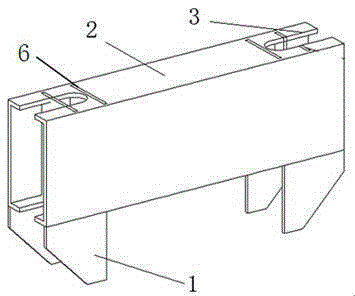
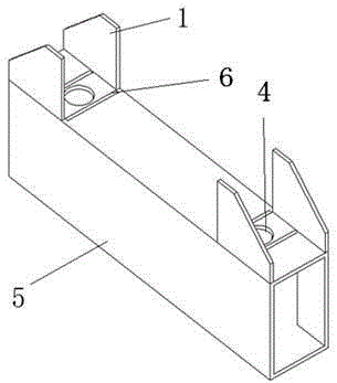
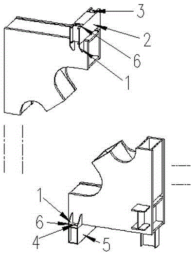
[0023] Such as Figure 1-Figure 2 The lifting device for a super high-altitude conversion truss includes an upper lifting beam 2 and a lower lifting beam 5 . Both ends of the upper lifting beam 2 are provided with upper reserved holes 3, the upper reserved holes 3 are arranged symmetrically with respect to the upper lifting beam 2, the upper reserved holes 3 run through the end edge of the upper lifting beam 2, and the two upper reserved holes The difference between the center distance between 3 and the width of the truss chord is 140mm. Both ends of the lower lifting beam 5 are provided with a lower reserved hole 4, which is symmetrically arranged with respect to the lower lifting beam 5, and the lower reserved hole 4 does not run through the end edge of the lower lifting beam 5, and the two lower reserved holes The difference between the center distance between the holes 4 and the width of the truss chord is 140mm. The reserved holes 3 on the upper part correspond to the r...

Embodiment 2

[0027] The structures and connection relations of a kind of ultra-high-altitude conversion truss lifting device in this embodiment are the same as those in Embodiment 1, and the different technical parameters are:

[0028] 1) The difference between the center distance between the two upper reserved holes 3 and the width of the truss chord is 170mm;

[0029] 2) The difference between the center distance between the two lower reserved holes 4 and the width of the truss chord is 170mm;

[0030] 3) The height of the lifting beam fixing piece 1 is 350mm, and the thickness is 20mm.

Embodiment 3

[0032] The structures and connection relations of a kind of ultra-high-altitude conversion truss lifting device in this embodiment are the same as those in Embodiment 1, and the different technical parameters are:

[0033] 1) The difference between the center distance between the two upper reserved holes 3 and the width of the truss chord is 200mm;

[0034] 2) The difference between the center distance between the two lower reserved holes 4 and the width of the truss chord is 200mm;

[0035] 3) The height of the lifting beam fixing piece 1 is 400mm, and the thickness is 25mm.


PUM


Abstract

The invention belongs to the field of constructing steel structures in civil building structures, and particularly relates to a superaltitude conversion truss lifting device which comprises an upper lifting device and a lower lifting device. The upper lifting device is characterized in that two ends of an upper lifting beam and two ends of a lower lifting beam are connected with a lifting beam fixing piece respectively, and an upper reserved hole is formed in each of the two ends of the upper lifting beam; the lower lifting device is characterized in that a lower reserved hole is formed in each of the two ends of the lower lifting beam, the upper reserved holes correspond to the lower reserved holes in position, and both the upper lifting beam and the lower lifting beam are perpendicularly connected onto a truss chord member through the lifting beam fixing pieces. The superaltitude conversion truss lifting device is small in size and light in weight and has no influence on the structure of a truss; the superaltitude conversion truss lifting device can be adjusted through the fixing pieces according to the size of the truss chord member, so that the applicable range of the superaltitude conversion truss lifting device is widened; a stressed reinforcing board is added at a lifting position inside each lifting beam, so that position strength of a positioning point is guaranteed; the superaltitude conversion truss lifting device is independently separated from the truss, thereby being capable of being mounted and demounted conveniently and high in practicability.

Description

technical field [0001] The invention relates to the field of steel structure construction in civil building structures, in particular to an ultra-high-altitude conversion truss lifting device. Background technique [0002] Super high-rise buildings refer to buildings with more than 40 floors and a height of more than 100 meters. With the development of science and technology today, super high-rise buildings appear widely in urban construction. The world's top ten super high-rise buildings are well-known, of which, 8 are in Asia, and 7 are in mainland China, Hong Kong and Taiwan. Super high-rise buildings embody the continuous progress of human science and technology civilization, and a large number of super high-rise buildings have also greatly changed the appearance of cities. [0003] In recent years, there have been more and more applications of steel structures in super high-rise buildings in various forms, among which the installation of steel structure transfer truss...

Claims


Application Information

Patent Timeline
Patent Type & Authority Applications(China)
IPC IPC(8): E04G21/16
Inventor 曹金玉孙善馥唐英琦杨深强龙海亮赵志涛陈磊马广超王志强
Owner CHINA CONSTR EIGHT ENG DIV CORP LTD
Why Eureka
Try Eureka