Guided recirculation intake fittings

An intake pipe and recirculation technology, applied in the direction of exhaust gas recirculation, engine components, machines/engines, etc., can solve the problems of increasing the airflow on the impeller, affecting the working efficiency of the impeller, and adversely affecting the supercharger, etc. Longevity, compact structure, low cost effect

Active Publication Date: 2018-05-01
CHONGQING PUSH MECHANISM
View PDF5 Cites 0 Cited by
  • Summary
  • Abstract
  • Description
  • Claims
  • Application Information

AI Technical Summary

Problems solved by technology

[0003] The existing recirculation intake pipe is a welded special-shaped three-way pipe, which cannot guide and mix the intake and recirculation gas, which is equivalent to the intake recirculation gas directly passing to the front of the supercharger. The airflow with a certain pressure will flow into the main channel and hit the compressor impeller of the supercharger. In this case, the angle and pressure of the airflow entering the impeller will change, which will increase the impact of the airflow on the impeller and affect the working efficiency of the impeller. At the same time, the airflow with strong pressure hits the impeller, and the vibration caused by the impact will also be abnormal, and the impeller is a high-speed rotating part, and long-term accumulation will have a bad effect on the supercharger

Method used


Image

  • Guided recirculation intake fittings

Examples


Embodiment Construction

[0014] The present invention will be further described below in conjunction with the embodiments and drawings.

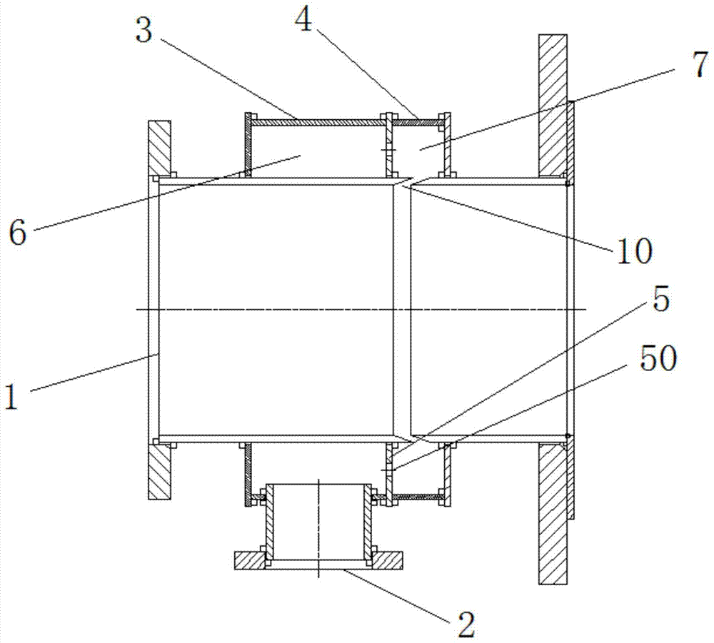
[0015] Such as figure 1 The shown recirculation intake pipe with guiding function includes a main pipe 1, and a first ring 3 and a second ring 4 are arranged side by side on the outside of the main pipe 1. The first ring 3 and the second ring A first loop cavity 6 and a second loop cavity 7 are formed between the channel 4 and the main pipe 1, and the first loop 3 and the second loop 4 are connected to the main pipe 1 by welding. The diameter of the first loop 3 and the second loop 4 are the same and larger than the outer diameter of the main pipe 1. The length of the first loop 3 is greater than the length of the second loop 4, so that the first loop cavity 6 The volume is greater than the volume of the second annular cavity 7, so that the circulating gas can smoothly enter the second annular cavity 7 from the first annular cavity 6 and ensure the normal air intake o...


PUM


Abstract

The invention discloses a recirculation intake pipe fitting with a guiding function, which includes a main pipe, and a first ring road and a second ring road are sheathed on the outside of the main pipe, and the first ring road and the second ring road are connected with the main pipe. A first ring channel cavity and a second ring channel cavity are formed between the pipes, and the first ring channel and the second ring channel are connected by a ring plate, and the ring plate is uniformly provided with circulation holes along the circumference. The side wall of the pipeline is also provided with an annular groove communicating with the second ring channel cavity. The annular groove is arranged obliquely along the side wall of the main pipeline. An air inlet pipe is vertically arranged outside the first ring road. The air inlet pipe is connected to the first ring road cavities connected. The air inlet pipe adopts the decompression structure of the side-by-side two-stage ring cavity, which is compact in structure, reduces the airflow loss while decompressing, and prevents the recirculation gas from entering the main flow channel. The inclined design of the annular groove has a guiding effect on the airflow, and It is convenient for processing and avoids adverse effects on the working efficiency of the supercharger compressor impeller due to the pressure and inlet angle of the recirculating gas.

Description

Technical field [0001] The invention relates to a recirculation intake pipe with guiding function, belonging to the field of gas recirculation systems. Background technique [0002] The loop pipe assembly is assembled between the mixed gas inlet pipe of the gas engine and the supercharger. It is the last pipe before the supercharger, that is, the mixed gas directly enters the compressor impeller of the supercharger after passing through this pipe. [0003] The existing recirculation intake pipe is a welded special-shaped three-way pipe, which cannot guide and mix the confluence of intake recirculation gas, which is equivalent to direct intake recirculation gas to the front of the supercharger. Airflow with a certain pressure will flow into the main flow path and hit the compressor impeller of the supercharger. In this case, the angle and pressure of the airflow entering the impeller will change, which will increase the impact of the airflow on the impeller and affect the efficiency...

Claims


Application Information

Patent Timeline
Patent Type & Authority Patents(China)
IPC IPC(8): F02M26/17
Inventor 黄雅婷丁超田海飞田华清
Owner CHONGQING PUSH MECHANISM
Why Eureka
Try Eureka