Cooling system of high water collecting tower

A cooling system and water collection tower technology, applied in water shower coolers, direct contact heat exchangers, heat exchanger types, etc., can solve the problems affecting peripheral circulating water cooling, small air flow resistance, improper matching, etc.

Active Publication Date: 2016-02-17
CHINA ENERGY ENG GRP GUANGDONG ELECTRIC POWER DESIGN INST CO LTD
View PDF7 Cites 1 Cited by
  • Summary
  • Abstract
  • Description
  • Claims
  • Application Information

AI Technical Summary

Problems solved by technology

The tower core material of the traditional high-level water collection tower basically adopts the uniform arrangement of water distribution pipes, equal height and density of water-spraying fillers, equal angles of water-receiving sloping plates, and equal length of water-receiving sloping plates. The guiding function of the flow channel between the water plates, the main heat and mass transfer area of ​​the upper part of the water collection device of the high-level water collection tower, especially above the filler, the air velocity is basically the highest at the center of the tower, while the air velocity in the area near the tower wall is relatively small; and the high-level The air flow resistance under the water collection

Method used


Image

  • Cooling system of high water collecting tower
  • Cooling system of high water collecting tower
  • Cooling system of high water collecting tower

Examples


Embodiment Construction

[0026] In order to make the object, technical solution and advantages of the present invention clearer, the present invention will be further described in detail below in conjunction with the accompanying drawings and specific implementation methods. It should be understood that the specific embodiments described here are only used to explain the present invention, and do not limit the protection scope of the present invention.

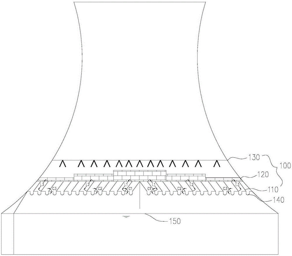
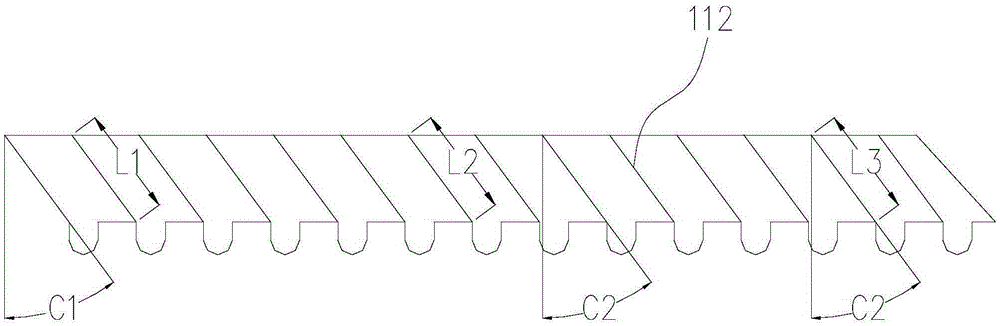
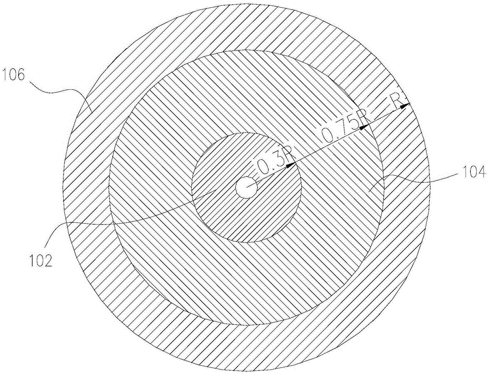
[0027] from figure 1 As shown, the cooling system of a high-level water collection tower according to the present invention includes a tower core device 100. The tower core device 100 takes the central axis of the high-level water collection tower as the center of the circle, and is divided into three annular distribution areas in turn: The inner area 102, the middle area 104 and the outer area 106, the tower core device 100 includes a packing device 120 and a water collection device 110; the packing device 120 includes a plurality of packing sheets (...


PUM


Abstract

The invention relates to a cooling system of a high water collecting tower. The cooling system comprises a tower core device. The tower core device is sequentially outwards divided into three annular distribution areas, namely, the inner area, the middle area and the outer area, with the center axis of the high water collecting tower as a circle center. The tower core device comprises a filler device and a water collecting device. The filler device comprises a plurality of filler pieces. The maximum distance between the adjacent filler pieces distributed in the inner area is a1, the maximum distance between the adjacent filler pieces distributed in the middle area is a2, the maximum distance between the adjacent filler pieces distributed in the outer area is a3, and a1<a2, or a1<a3. The water collecting device comprises a plurality of water collecting inclined plates. The length of the water collecting inclined plates distributed in the inner area is L1, the length of the water collecting inclined plates distributed in the middle area is L2, the length of the water collecting inclined plates distributed in the outer area is L3, L1<L2, or L1<L3. According to the cooling system of the high water collecting tower, the cooling efficiency of the high water collecting tower can be improved, and the output water temperature of a cooling tower can be lowered.

Description

technical field [0001] The invention relates to the technical field of high-level water collection towers, in particular to a cooling system for high-level water collection towers. Background technique [0002] The high-level water collection tower is one of the important thermal equipment in large-scale power plants, and its operating performance has a great influence on the safety and economy of the power plant. The tower core material of the traditional high-level water collection tower basically adopts the uniform arrangement of water distribution pipes, equal height and density of water-spraying fillers, equal angles of water-receiving sloping plates, and equal length of water-receiving sloping plates. The guiding function of the flow channel between the water plates, the main heat and mass transfer area of ​​the upper part of the water collection device of the high-level water collection tower, especially above the filler, the air velocity is basically the highest at t...

Claims


Application Information

Patent Timeline
IPC IPC(8): F28F25/08F28F25/04
Inventor 何辉龙国庆毛卫兵何小华唐刚曾令刚汪芬张国罡
Owner CHINA ENERGY ENG GRP GUANGDONG ELECTRIC POWER DESIGN INST CO LTD
Why Eureka
Try Eureka