
Optical measurement method and device for deformation and strain of high-speed rotating structural parts

A high-speed rotation and optical measurement technology, which is applied in the direction of measuring devices, optical devices, instruments, etc., can solve the problems of high cost, high equipment requirements, and low rotation speed

Active Publication Date: 2017-12-29
TSINGHUA UNIV
View PDF8 Cites 0 Cited by
  • Summary
  • Abstract
  • Description
  • Claims
  • Application Information

AI Technical Summary

Problems solved by technology

[0004] The currently implemented optical measurement methods and devices for deformation / strain of rotating structural parts generally have low rotation speeds, which cannot meet the measurement requirements of energy storage flywheels, power turbines, and electric spindles rotating at high speeds above 10,000 rpm and ultra-high speeds above 30,000 rpm.
In experimental equipment, short-time shutter and high frame rate industrial cameras are often used to capture images of rotating workpieces, which requires high equipment requirements and high costs

Method used


Image

  • Optical measurement method and device for deformation and strain of high-speed rotating structural parts
  • Optical measurement method and device for deformation and strain of high-speed rotating structural parts
  • Optical measurement method and device for deformation and strain of high-speed rotating structural parts

Examples


Embodiment Construction

[0061] The present invention will be further described below in conjunction with the embodiments and the accompanying drawings.

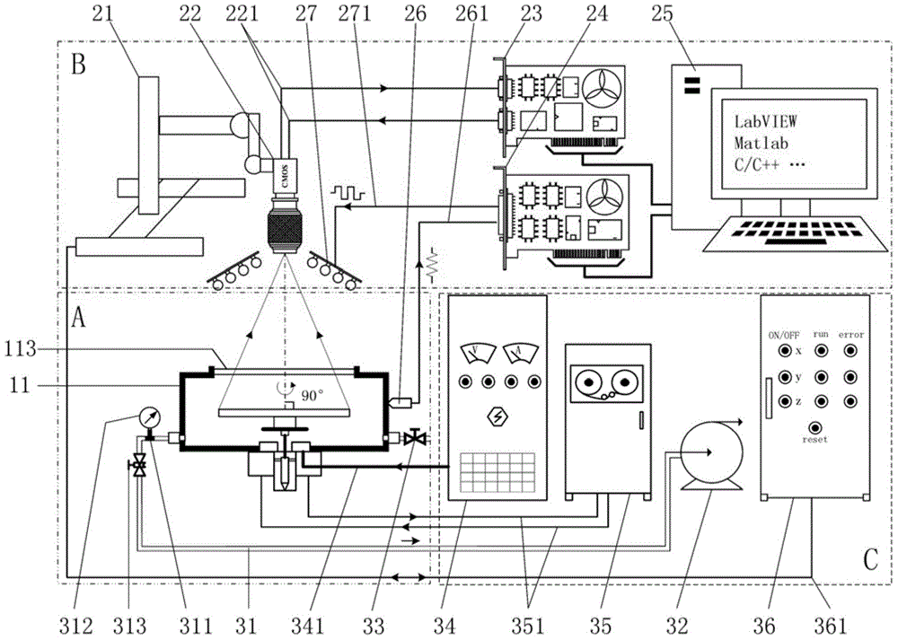
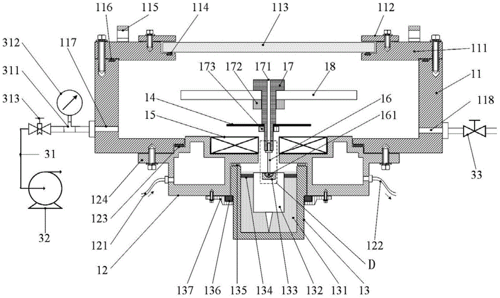
[0062] figure 1 It is a general structure diagram of the optical measuring device for deformation and strain of high-speed rotating structural parts. The optical measuring device for deformation and strain of high-speed rotating structural parts consists of high-speed rotating system A for thin disc-shaped axisymmetric structural parts, image acquisition and signal processing system B and test assistants. The system C is composed of the high-speed rotation system A of the thin disk-shaped axisymmetric structure to rotate the thin disk-shaped axisymmetric structure test piece at high speed, and the image acquisition and signal processing system B obtains the image signal of the thin disk-shaped axisymmetric structure test piece and the illumination source. Trigger signal, test auxiliary system C provides vacuum power supply, disk motor power supply ...


PUM


Abstract

The invention belongs to the field of rotating machinery experimental mechanics, and specifically relates to an optical measuring method and apparatus for deformation and strain of a high speed rotating structural member. The optical measuring apparatus comprises a high speed rotating system for a thin disk-shaped axisymmetric structural member, an image acquisition and signal processing system and an auxiliary test system, wherein the surface of a test member of the thin disk-shaped axisymmetric structure is coated with a pattern of concentric circles and a vertical ultra high-speed rotating axis is formed; a disk type variable frequency motor is used to drive the single-point supported vertical ultra high-speed rotating axis in a vacuum chamber; a common low-speed digital camera is used to acquire the surface pattern of concentric circles of the high-speed rotating thin disc-shaped axisymmetric structure test member under the irradiation of a stroboscopic light source; and the image identification technology is used to acquire the pattern change information and obtain deformation and strain of the high speed rotating test member after processing the pattern change information. The optical measuring method and apparatus for deformation and strain of a high speed rotating structural member can acquire the stress information by measuring changes of the radius of the concentric circles, and are suitable for the mechanical robustness testing field of high speed and ultra high-speed rotating structural member, wherein the rotating speed is greater than 10000rpm.

Description

technical field [0001] The invention belongs to the field of experimental mechanics of rotating machines, in particular to an optical measurement method and device for deformation and strain of high-speed rotating structural parts. Background technique [0002] The deformation and strain measurement of rotating structural parts has always been a problem worthy of attention in the field of experimental mechanics of rotating machines. Some scholars proposed to use the "panoramic Moiré contour method" and "slit high-speed camera" to measure the deformation of rotating objects. Non-contact infrared telemetry and ultrasonic telemetry have also been tried in the stress and strain measurement of high-speed rotating components. Foreign scholars draw patterns on the surface of the rotating disk to form a special "photoelectric sensor" reflective layer, and the change of duty cycle at different radial positions under high-speed rotation reflects the deformation characteristics. Base...

Claims


Application Information

Patent Timeline
Patent Type & Authority Patents(China)
IPC IPC(8): G01B11/16
CPCG01B11/16
Inventor 戴兴建汪勇张小章
Owner TSINGHUA UNIV
Learn More