High voltage cable fault section positioning and monitoring device

A technology for high-voltage cables and fault zones, applied to fault locations, signal transmission systems, instruments, etc., can solve problems such as the influence of timely restoration of power supply, damage to insulators and wire facilities, and inaccurate fault location, so as to achieve accurate and reliable positioning results. Normal work, the effect of short propagation medium distance

Inactive Publication Date: 2016-02-17
ANHUI ZHIXIN ENERGY TECH CO LTD
View PDF5 Cites 2 Cited by
  • Summary
  • Abstract
  • Description
  • Claims
  • Application Information

AI Technical Summary

Problems solved by technology

[0002] Transmission line fault tripping is one of the most frequent accidents in the high-voltage power grid. In addition to impacting the system, each tripping accident will cause damage to insulators, wires and other facilities, leaving a safety hazard for the system operation
Due to the inaccurate fault location, it takes a long time to find and repair the fault, which affects the timely restoration of power supply. These problems are more prominent problems in the production practice of high-voltage power grids
[0003] At present, power systems often use traveling waves to locate transmission line faults, but traveling waves are more reliable when applied to short-distance media. In the process of long-distance media propagation, the change of propagation wave speed will cause large errors in positioning accuracy.
On the other hand, the temperature of the conductor during the operation of the power cable is an important basis for determining its current carrying capacity. If the cable is overheated, it will cause insulation damage

Method used


Image

  • High voltage cable fault section positioning and monitoring device

Examples


Embodiment Construction

[0015] The present invention will be described in detail below with reference to the accompanying drawings and in combination with embodiments.

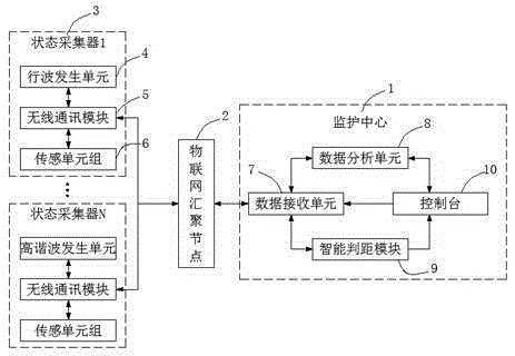
[0016] The high-voltage cable fault zone positioning and monitoring device described in this embodiment, such as figure 1 As shown, it includes a monitoring center 1, an Internet of Things convergence node 2, and a number of cable running status collectors 3 evenly distributed between high-voltage cable lines, and the distance between the status collectors 3 is 5-10km.

[0017] The state collector 3 includes a traveling wave generating unit 4, a wireless communication module 5 and a sensing unit group 6, and the sensing unit group 6 includes a temperature sensor and a humidity sensor. The monitoring center 1 includes a data receiving unit 7, a data analysis unit 8, an intelligent distance judgment module 9 and a console 10, and the traveling wave generation unit 4 and the sensing unit group 6 pass through the wireless communication m...


PUM


Abstract

The invention discloses a high voltage cable fault section positioning and monitoring device which comprises a monitoring center, an internet of things aggregation node and multiple cable operating state acquisition units, wherein each state acquisition unit comprises a traveling wave generating unit, a wireless communication module and a sensor unit group; the monitoring center comprises a data receiving unit, a data analysis unit, an intelligent distance judgment module and a control console; the traveling wave generating units and the sensor unit groups wirelessly communicate with one another by virtue of the wireless communication module, the internet of things aggregation node and the data receiving unit; one end of the data receiving unit communicates by virtue of the data analysis unit / intelligent distance judgment module and the control console. According to the device disclosed by the invention, the propagation medium distance is shortened by arranging the multiple state acquisition units between high voltage cable circuits, so that the traveling wave positioning result is accurate and reliable. Meanwhile, the sensor unit groups are arranged in the state acquisition units, so that potential faults can be discovered, the condition that destruction of insulation is caused due to overtemperature of the cable is avoided, repair and maintenance are timely performed, and normal operation of power cables is guaranteed.

Description

technical field [0001] The invention relates to the field of power system equipment, in particular to a high-voltage cable fault zone positioning and monitoring device. Background technique [0002] Transmission line fault tripping is one of the most frequent accidents in high-voltage power grids. In addition to impacting the system, each tripping accident will cause damage to insulators, wires and other facilities, leaving hidden dangers to system operation. Due to the inaccurate fault location, it takes a long time to find and repair the fault, which affects the timely restoration of power supply. These problems are more prominent problems in the production practice of high-voltage power grids. [0003] At present, power systems often use traveling waves to locate transmission line faults, but traveling waves are more reliable when applied to short-distance media. In the process of long-distance media propagation, the change of propagation wave speed will cause large error...

Claims


Application Information

Patent Timeline
Patent Type & Authority Applications(China)
IPC IPC(8): G01R31/08G08C17/02
CPCY04S10/52
Inventor 张颂红柳文钦柳安柳绿洲
Owner ANHUI ZHIXIN ENERGY TECH CO LTD
Why Eureka
Try Eureka