Mirror reflection based radar for obstacle avoidance of unmanned aerial vehicles

A specular reflection, unmanned aerial vehicle technology, used in the reflection/re-radiation of radio waves, the use of re-radiation, radio wave measurement systems, etc., can solve the problems of complex motor equipment, increase costs, etc., to simplify the motor structure and reduce costs. , the effect of low cost

Inactive Publication Date: 2016-02-17
袁帅
12 Cites 12 Cited by

AI-Extracted Technical Summary

Problems solved by technology

The first solution requires complex motor equipment and is not suitable for small UAVs
The s...

Abstract

The invention discloses a mirror reflection based radar for the obstacle avoidance of unmanned aerial vehicles, which comprises a radar shell (1), a millimeter-wave radar front-end and baseband processing circuit (2), a millimeter-wave radar lens (3) and a rotating mirror (4), wherein the millimeter-wave radar front-end and baseband processing circuit (2) is arranged in the bottom side of the radar shell (1), the millimeter-wave radar lens (3) is arranged above the millimeter-wave radar front-end and baseband processing circuit (2), the rotating mirror (4) is arranged above the millimeter-wave radar lens (3), and the rotating mirror (4) is connected with a motor (5). The radar for the obstacle avoidance of unmanned aerial vehicles provided by the invention is reasonable in structure design and low in cost, and can be applied to small unmanned aerial vehicles. According to the invention, by using the advantage of millimeter-wave beam aggregation, the radar achieves 360-degree detection through a rotating lens but without using the radar, so that the structure of the motor can be simplified; and compared with phase-position radars, only a radar transceiver module is required in the invention, so that the cost is greatly decreased, and the applicability is strong.

Application Domain

Technology Topic

Image

  • Mirror reflection based radar for obstacle avoidance of unmanned aerial vehicles
  • Mirror reflection based radar for obstacle avoidance of unmanned aerial vehicles

Examples

  • Experimental program(1)

Example Embodiment

[0018] Below in conjunction with accompanying drawing and specific embodiment, further illustrate the present invention, should be understood that these embodiments are only for illustrating the present invention and are not intended to limit the scope of the present invention, after having read the present invention, those skilled in the art will understand various aspects of the present invention Modifications in equivalent forms all fall within the scope defined by the appended claims of this application.
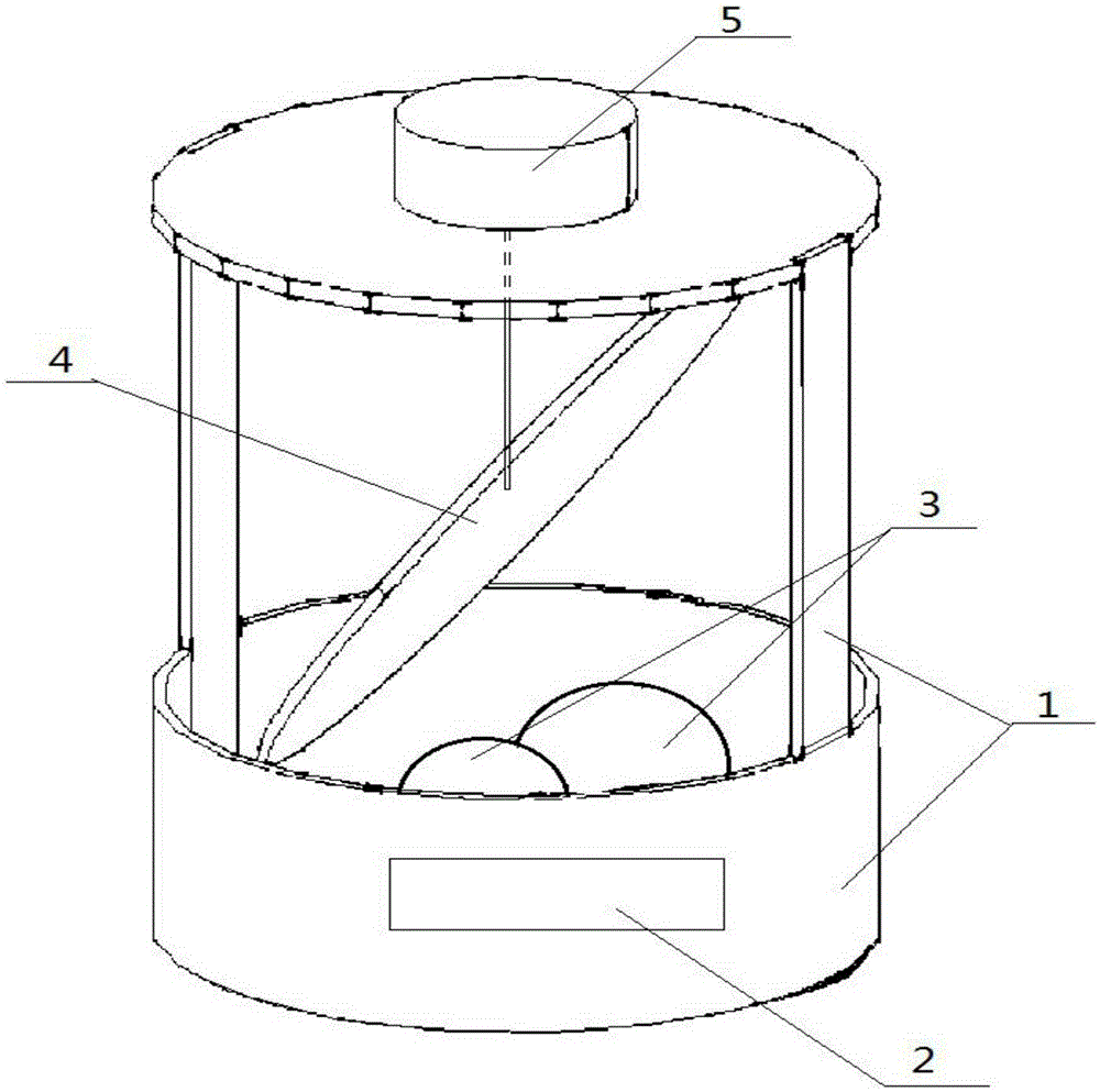
[0019] like figure 1 and figure 2 As shown, a UAV obstacle avoidance radar based on specular reflection, it includes a radar housing (1), a millimeter-wave radar front end and a baseband processing circuit (2) installed inside the bottom side of the radar housing (1), installed in the millimeter The millimeter-wave radar lens (3) above the wave radar front end and the baseband processing circuit (2), the rotating mirror (4) installed above the millimeter-wave radar lens (3), the rotating mirror (4) is connected with the motor (5), and the motor (5) Installed on the top of the radar housing (1).
[0020] In the aforementioned mirror-reflection-based UAV obstacle avoidance radar, the number of millimeter-wave radar lenses (3) is one or two.
[0021] In the aforementioned mirror reflection-based UAV obstacle avoidance radar, the rotating mirror (4) is at an angle of 45° to the horizontal direction.
[0022] A kind of unmanned aerial vehicle obstacle avoidance radar based on specular reflection as described above, described millimeter-wave radar front-end and baseband processing circuit (2) comprise millimeter-wave front-end circuit and antenna, the intermediate frequency filter that links to each other with millimeter-wave front-end circuit and antenna An amplification module (2-1), an analog-to-digital conversion module (2-2) connected to the intermediate frequency filter amplification module (2-1), a digital signal processing module (2-3) connected to the analog-to-digital conversion module (2-2) ).
[0023] The above is only a preferred embodiment of the present invention, it should be pointed out that, for those of ordinary skill in the art, without departing from the principle of the present invention, some improvements and modifications can also be made, and these improvements and modifications can also be made. It should be regarded as the protection scope of the present invention.

PUM

no PUM

Description & Claims & Application Information

We can also present the details of the Description, Claims and Application information to help users get a comprehensive understanding of the technical details of the patent, such as background art, summary of invention, brief description of drawings, description of embodiments, and other original content. On the other hand, users can also determine the specific scope of protection of the technology through the list of claims; as well as understand the changes in the life cycle of the technology with the presentation of the patent timeline. Login to view more.

Similar technology patents

Physical simulation experiment method and device for monitoring shearing force of earthquake triggering cross section surface

ActiveCN101609157AReal-time warning and forecastReasonable structural designForce measurementSeismologySeismic hazardMechanical models
Owner:CHINA UNIV OF MINING & TECH (BEIJING)

Classification and recommendation of technical efficacy words

  • Reasonable structural design
  • Low cost

Semiconductor device

InactiveUS6975142B2Low costReduce manufacturing stepsTransistorSolid-state devicesVoltage amplitudeSemiconductor
Owner:SEMICON ENERGY LAB CO LTD
Why Eureka
Try Eureka