Dotted groove type optical fiber cladding surface Bragg raster

A technology of optical fiber cladding and dot-shaped grooves, which is applied in the direction of grating fiber, cladding fiber, optical waveguide and light guide, etc., can solve the problems of poor control of the process, reduce the mechanical strength of FBG, and difficult operation, and achieve low temperature/strain Cross-sensitivity effect, obvious birefringence effect, and simple production method

Inactive Publication Date: 2016-02-17
CHONGQING UNIV OF TECH
View PDF6 Cites 16 Cited by
  • Summary
  • Abstract
  • Description
  • Claims
  • Application Information

AI Technical Summary

Problems solved by technology

However, there are many shortcomings in the method of chemical etching or side grinding of the FBG cladding, such as: the uniformity of the grating surface cannot be guaranteed, so the resonant spectrum of the grating is broadened, resulting in a decrease in the measurement accuracy in the sensor, or even unusable; The high mechanical strength makes it difficult to operate and easy to break during use; the process of chemical corrosion or side grinding takes a long time, the process is not easy to control, and the repeatability is not good
And at present, there is no relevant report both at home and abroad for the point-shaped groove type optical fiber cladding surface Bragg grating sensor proposed by the present invention.

Method used


Image

  • Dotted groove type optical fiber cladding surface Bragg raster
  • Dotted groove type optical fiber cladding surface Bragg raster
  • Dotted groove type optical fiber cladding surface Bragg raster

Examples


Embodiment Construction

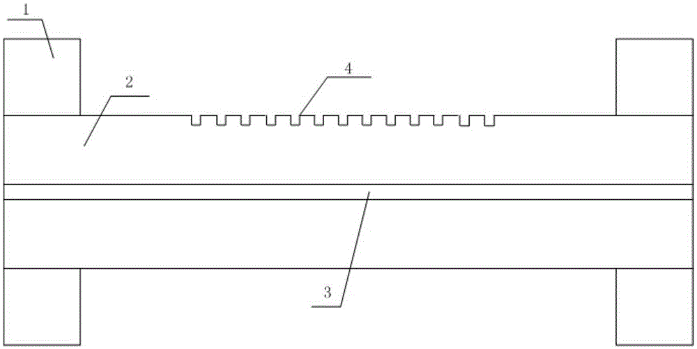
[0016] see figure 1 , a Bragg grating on the surface of a point-shaped groove-type fiber cladding, comprising: a fiber coating 1, a fiber cladding 2, and an optical fiber core 3; the fiber cladding surface Bragg grating 4 is arranged on the fiber cladding 2 of a single-mode fiber The outer surface of the fiber cladding surface; the fiber cladding surface Bragg grating 4 is composed of several point-shaped grooves, and several point-shaped grooves are distributed periodically along the axial direction of the optical fiber, and the outer surface of the optical fiber cladding is structurally Damage; the center points of all point-shaped grooves are located on a straight line, which is parallel to the central axis of the fiber; the groove depth of the point-shaped grooves is <0.5μm, and the groove width is less than half of the period of the Bragg grating on the surface of the fiber cladding; the The length of the Bragg grating on the surface of the fiber cladding is between 1 mm ...


PUM


Abstract

The invention discloses a dotted groove type optical fiber cladding surface Bragg raster, which is characterized in that the optical fiber cladding surface Bragg raster is arranged on the outer surface of the optical fiber cladding of the single mode fiber; the optical fiber cladding surface Bragg raster consists of a plurality of dotted grooves which cause the structural damage to the optical fiber cladding and have periodicity; and the center points of all dotted grooves are in the same line which is parallel with a center axis of the optical fiber. The dotted groove type optical fiber cladding surface Bragg raster is unique in structure, simple in manufacture method, miniaturized and fiber-optical. The invention has a characteristic sensitive to the outside medium, which is similar to the long period optical fiber bragg gating, has a high Q value factor and has a cross sensitivity effect which is much lower than the long period optical fiber bragg gating; the temperature, pressure and the strain sensitivity are higher than that of the traditional optical fiber Bragg raster; the raster zone of the optical fiber cladding has obvious double refraction effect and can be widely applicable to the fields like the biology, chemical engineering, medical science, the bioscience, etc.

Description

technical field [0001] The invention relates to an optical fiber grating, in particular to a Bragg grating on the cladding surface of a point-shaped groove type optical fiber. Background technique [0002] Information technology and sensor technology represented by optical fiber communication and optical fiber sensing technology have greatly promoted the progress of human society since the 1970s. Fiber Bragg gratings can be divided into two basic types according to the period size: fiber Bragg grating (ie, FBG, period less than 1 μm) and long-period fiber grating (period tens to hundreds of μm). At present, the most commonly used method for fabricating FBG is the phase mask method based on ultraviolet exposure, which requires the optical fiber material to be photosensitivity, and needs to increase its photosensitivity by carrying hydrogen. In 2007, I.Bennion of Aston University in the United Kingdom successfully wrote first-order, second-order and fourth-order Bragg grating...

Claims


Application Information

Patent Timeline
Patent Type & Authority Applications(China)
IPC IPC(8): G02B6/02
CPCG02B6/0208
Inventor 罗彬彬
Owner CHONGQING UNIV OF TECH
Why Eureka
Try Eureka