Check patentability & draft patents in minutes with Patsnap Eureka AI!

A gate protection circuit driven by igbt

A protection circuit and protection resistor technology, applied in electronic switches, electrical components, output power conversion devices, etc., can solve problems such as inability to use drive adapter boards, narrowing of IGBT pulse widths, and little research on protection circuits. Guarantee safe and reliable operation, realize protection function, and have the effect of strong versatility

Active Publication Date: 2018-11-20
BEIJING CED RAILWAY ELECTRIC TECH
View PDF5 Cites 0 Cited by
  • Summary
  • Abstract
  • Description
  • Claims
  • Application Information

AI Technical Summary

Problems solved by technology

[0003] Under normal circumstances, the IGBT gate voltage VGE needs 15v to make the IGBT enter deep saturation; when VGE increases, the collector-emitter voltage VCE will decrease when it is turned on, and the turn-on loss will decrease accordingly, but VGE will increase during the load short circuit process. The collector current Ic will also increase accordingly, so that the pulse width that the IGBT can withstand short-circuit damage is narrowed, and it also limits the short-circuit current and the stress it brings (in equipment with a short-circuit working process, such as used in motors For IGBT, +VGE should try to select the minimum value under the condition of meeting the requirements, so as to improve its short-circuit resistance capability)
[0004] In the prior art, the rising edge and falling edge control technology of the IGBT gate has been paid more and more attention, that is, an adjustable driving voltage waveform is applied to the IGBT gate to control the IGBT turn-on and turn-off process to achieve the required turn-on and turn-off. However, there is little research on protection circuits for different gate levels, and more complex control methods are often used, which makes it impossible to reduce the influence of parasitic parameters on the drive by using the drive adapter board
in addition, figure 1 Once the voltage regulation value of the two anti-phase series Zener diodes Z1 and Z2 is selected, only a certain fixed gate level can be clamped and protected, and the driving scheme of VGE level change is not applicable.

Method used


Image

  • A gate protection circuit driven by igbt
  • A gate protection circuit driven by igbt

Examples


Embodiment Construction

[0022] The technical solutions in the embodiments of the present invention will be clearly and completely described below in conjunction with the accompanying drawings in the embodiments of the present invention. Obviously, the described embodiments are only some of the embodiments of the present invention, not all of them. Based on the embodiments of the present invention, all other embodiments obtained by persons of ordinary skill in the art without making creative efforts belong to the protection scope of the present invention.

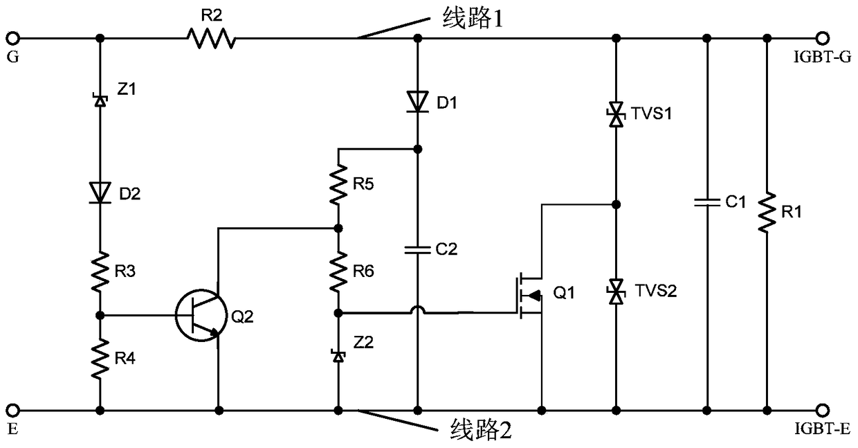
[0023] An embodiment of the present invention provides a gate protection circuit driven by an IGBT, which, as a part of the IGBT drive circuit, can be directly installed on an adapter board of an IGBT module. Such as figure 2 As shown, it mainly includes: the port G and the port E connected to the drive board to output the driving pulse signal, the port IGBT-G connected to the IGBT gate and the port IGBT-E connected to the IGBT emitter; the port G...


PUM


Abstract

The invention discloses an IGBT-driven grid electrode protection circuit. The circuit is improved based on a typical grid electrode protection circuit, so that the protection of voltage peaks and transient surges of different grid electrodes can be realized; in addition, according to the different grid electrode levels, the circuit implements protection of different protection threshold values, so that the circuit has a simple structure, is strong in universality and reliability, not only can implement the protection function of the grid electrode protection circuit in the IGBT driving, guarantee the safe and reliable operation of an IGBT converter, also can automatically switch protection threshold values of two different driving pulse levels, and is adaptive to the development of different levels.

Description

technical field [0001] The invention relates to the technical field of power electronics, in particular to an IGBT-driven gate protection circuit. Background technique [0002] IGBT (Insulated Gate Bipolar Transistor) failure is mainly caused by overvoltage / overcurrent of collector and emitter and overvoltage / overcurrent of gate. In order to prevent the accumulation of gate charge and the peak of the gate-source voltage from damaging the IGBT - some protection elements can be set between the G pole and the E pole, such as figure 1 The role of the resistor RGE is to discharge the accumulated charge on the gate; the two reverse-series Zener diodes Z1 and Z2 are to prevent the gate-source voltage spike from damaging the IGBT, and the on-resistance RG and capacitor C parameters can improve the drive pulse The rate of change of voltage and current. [0003] Under normal circumstances, the IGBT gate voltage VGE needs 15v to make the IGBT enter deep saturation; when VGE increases...

Claims


Application Information

Patent Timeline
Patent Type & Authority Patents(China)
IPC IPC(8): H02M1/08H03K17/08
CPCH02M1/08H03K17/08
Inventor 贺觅知徐玉峰王传芳
Owner BEIJING CED RAILWAY ELECTRIC TECH
Features
  • R&D
  • Intellectual Property
  • Life Sciences
  • Materials
  • Tech Scout
  • Unparalleled Data Quality
  • Higher Quality Content
  • 60% Fewer Hallucinations
Learn More