Turbine and method for detecting rubbing

A technology of turbines and gas turbines, which is applied to the monitoring system of structure noise, gas turbines, and the field of friction detection in turbines, to achieve the effect of simple positioning friction

Inactive Publication Date: 2016-02-17
SIEMENS AG
View PDF8 Cites 1 Cited by
  • Summary
  • Abstract
  • Description
  • Claims
  • Application Information

AI Technical Summary

Problems solved by technology

[0007] However, currently known systems only allow basic detection of friction

Method used


Image

  • Turbine and method for detecting rubbing
  • Turbine and method for detecting rubbing
  • Turbine and method for detecting rubbing

Examples


Embodiment Construction

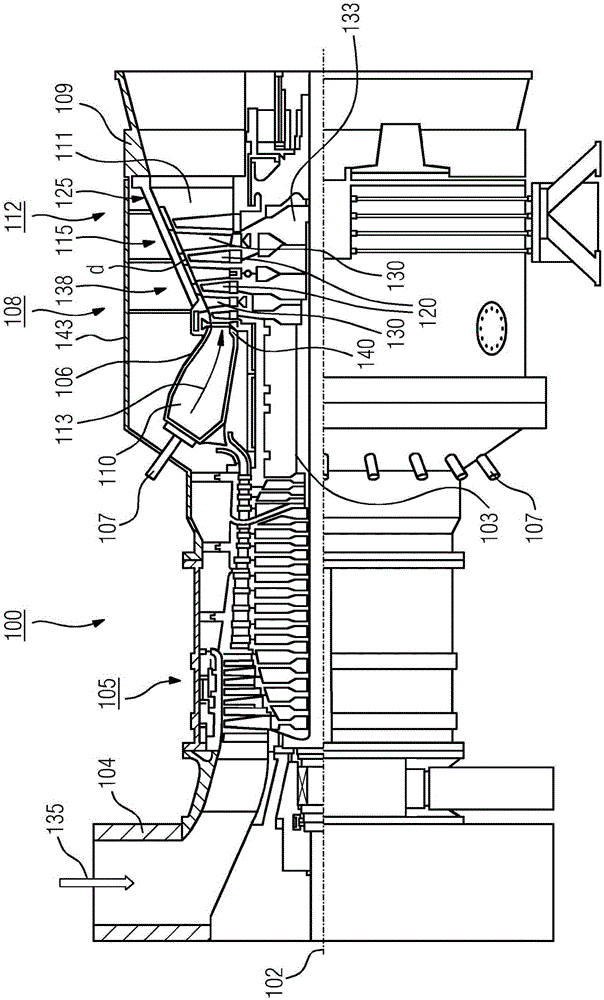
[0026] figure 1 A turbine 100 , here a gas turbine, is shown in partial longitudinal section. The gas turbine 100 has an internally mounted rotor 103 , also referred to as a turbine rotor, such that it can rotate about an axis of rotation 102 (axial direction). An intake casing 104 , a compressor 105 , an annular combustion chamber 110 with a plurality of coaxially arranged combustors 107 , especially an annular combustion chamber 106 , a turbine 108 and an exhaust casing 109 are arranged in sequence along the rotor 103 .

[0027] The annular combustion chamber 106 communicates with the annular hot gas channel 111 . There, for example, four turbine stages 112 are connected one behind the other to form turbine 108 . Each turbine stage 112 is formed by a ring of two blades. As seen in the flow direction of the working medium 113 , the row 125 formed by the rotor blades 120 follows the hot gas channel 111 of the row 115 of guide vanes.

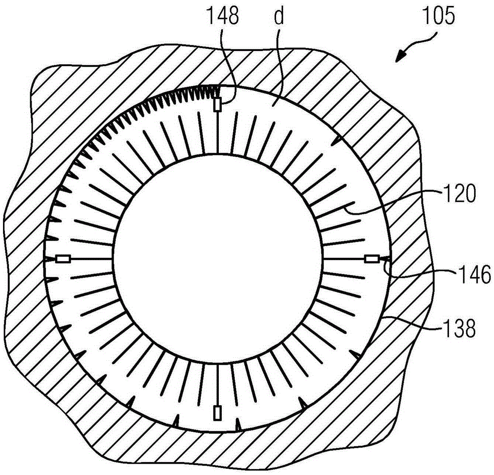
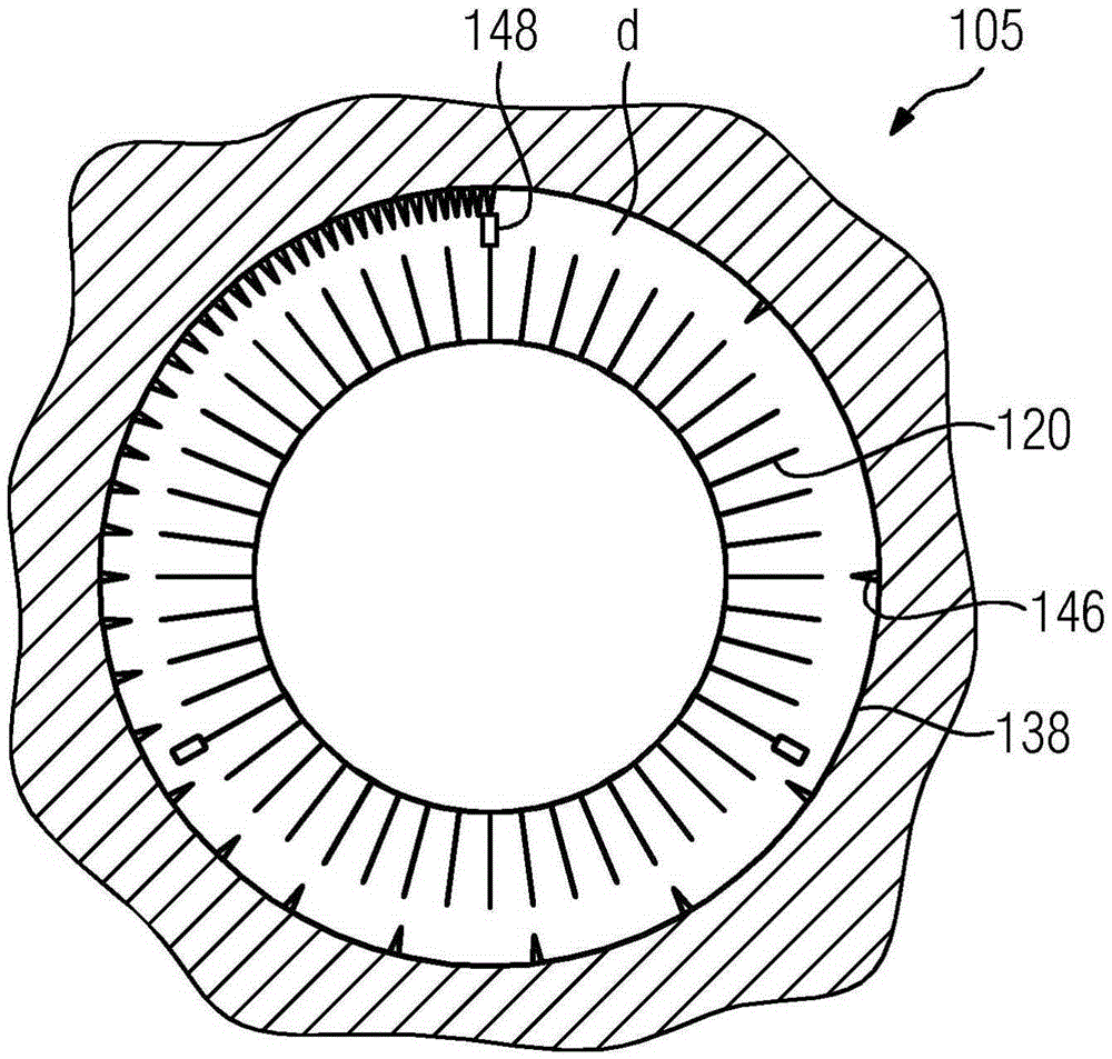
[0028] Guide vanes 130 are fixed to st...


PUM


Abstract

It is intended that a turbine (100), in particular a gas turbine, comprising a rotor (103), a housing (138) spaced from the rotor (103) by a gap (d), and a system for monitoring structure-borne noise, permit rubbing of the rotor and the housing to be localised with the least possible technical complexity. For this purpose, in both a first and second axial region, one or more inwardly directed rubbing teeth (146) of the housing (138) and one or more outwardly directed rubbing edges (148) of the rotor (103) are arranged, wherein the one or more rubbing teeth (146) and the one or more rubbing edges (148) are distributed along the circumference in such a way that contact of the particular rubbing teeth (146) and rubbing edges (148) at a specified rotational frequency of the rotor (103) occurs at a different frequency in the first axial region than in the second axial region.

Description

technical field [0001] The invention relates to a turbomachine, in particular a gas turbine, comprising a rotor, a casing separated from the rotor by a gap, and a system for monitoring structure-borne noise. It further relates to a method for detecting friction in a turbomachine, in particular a gas turbine comprising a rotor, a casing isolated from the rotor by a gap, and a system for monitoring structure-borne noise. Background technique [0002] A turbine is a fluid machine that converts the internal energy (enthalpy) of a fluid (liquid or gas) into rotational energy and ultimately into mechanical transmission energy. A portion of the internal energy is extracted from the liquid flow by the flow around the turbine blades, which may be free swirling and laminar flow, and the energy is transferred to the rotor blades of the turbine. The turbine shaft is then rotated by the latter; the available power is output to a coupled working machine, such as a generator. The rotor b...

Claims


Application Information

Patent Timeline
Patent Type & Authority Applications(China)
IPC IPC(8): F01D11/22F01D21/04
CPCF01D11/22F01D21/04F01D5/02F01D21/003F01D25/24F05D2220/32F05D2240/24F05D2260/83
Inventor A·塞罗卡R·科斯塔玛格纳U·塞伯
Owner SIEMENS AG
Why Eureka
Try Eureka