Stability control method and device for optical parameters of optical fiber perform

An optical fiber preform and stability control technology, which is applied to glass manufacturing equipment, manufacturing tools, etc., can solve the problems of not mentioning the influence of the uniformity of exhaust wind speed on the deposition efficiency of the preform surface, and achieve the consistency of control deposition, Consistent effect of deposition efficiency

Active Publication Date: 2016-02-24
ZHONGTIAN TECH ADVANCED MATERIALS CO LTD +1
View PDF8 Cites 7 Cited by
  • Summary
  • Abstract
  • Description
  • Claims
  • Application Information

AI Technical Summary

Problems solved by technology

However, the patent does not mention the influence of the uniformity of exhaust air velocity on the surface deposition efficiency of the preform

Method used


Image

  • Stability control method and device for optical parameters of optical fiber perform
  • Stability control method and device for optical parameters of optical fiber perform
  • Stability control method and device for optical parameters of optical fiber perform

Examples


Embodiment 1

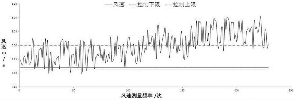
[0054] Turn on the wind speed detection and processor 8 to monitor the wind speed in real time, turn off the signal feedback function, and keep the initial position of the air valve opening of the exhaust pipe unchanged.

[0055] After the deposition, the results of the offset and deposition volume of each air duct are as follows:

[0056] Duct number 1# 2# 3# 4# 5# Initial wind speed m / s 7.98 8.00 7.99 8.00 7.98 End wind speed m / s 8.01 8.03 8.05 8.01 8.00 Offset ratio % 0.38 0.37 0.75 0.12 0.25 Preform Deposition Offset % 0.33 0.32 1.21 0.00 0.15 Preform Drawing Optical Parameters (MFD) Offset % 0.16 0.15 0.92 0.00 0.08

[0057] Among them, the deviation of the deposition amount of the optical fiber preform is judged based on the position of the 4# air duct with the minimum deviation of the wind speed. It can be seen that where the wind speed offset is relatively large, the deposition amount of the optical fib...

Embodiment 2

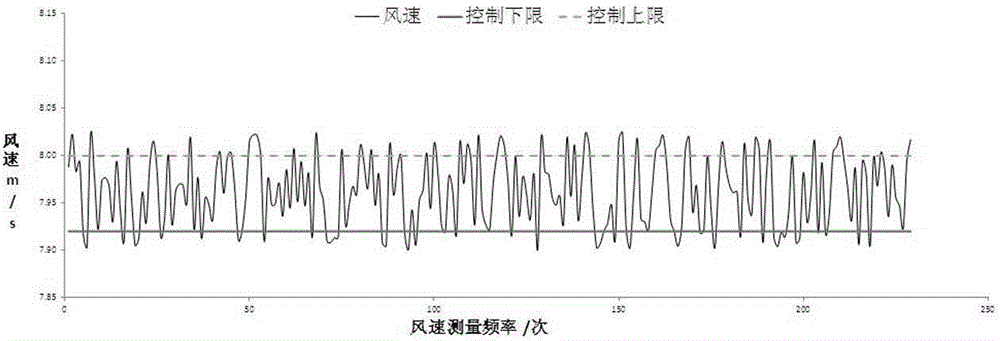
[0060] The wind speed detection and processor 8 are turned on for real-time wind speed monitoring, the signal feedback function is turned on, and the air valve opening of the exhaust pipe is automatically adjusted online.

[0061] After the deposition, the results of the offset and deposition volume of each air duct are as follows:

[0062] Types of 1# 2# 3# 4# 5# Initial wind speed m / s 7.98 8.00 7.99 8.00 7.98 End wind speed m / s 8.01 8.03 8.05 8.01 8.00 Offset ratio % -0.12 0.00 0.00 -0.12 0.12 Preform Deposition Offset % 0.08 0.00 0.01 0.06 0.01 Preform Drawing Optical Parameters (MFD) Offset % 0.05 0.00 0.00 0.03 0.01

[0063] Among them, the deviation of the deposition amount of the optical fiber preform is judged based on the position of the 2# air duct with the minimum wind speed deviation. It can be seen that the wind speed fluctuation is controlled at about 0.1%, the deposition amount of the optical f...


PUM


Abstract

The invention relates to a stability control method and device for the optical parameters of an optical fiber perform. The device comprises a deposition cavity, exhaust pipelines, exhaust pipe air valves, air valve opening controllers, air speed measurement rods, an air valve opening controller signal line, an air speed measurement rod signal line and an air speed detecting and processing unit. The exhaust pipelines are horizontally installed over the deposition cavity in the axial direction of the optical fiber perform, the air speed measurement rods are installed on the inner walls of the exhaust pipelines, the tail ends of the air speed measurement rods are installed at the centers of the exhaust pipelines, the exhaust pipe air valves are installed above the air speed measurement rods, the opening of the air valves is controlled by the external air valve opening controllers, temperature signals of the air speed measurement rods are connected into the air speed detecting and processing unit through the air speed measurement rod signal line, the air speed detecting and processing unit feeds instructions back to the air valve opening controllers through the air valve opening controller signal line, and then the air valve opening controllers control the opening of the exhaust pipe air valves so as to control the air speed.

Description

technical field [0001] The invention relates to a method and equipment for controlling the stability of optical parameters of an optical fiber preform rod. Background technique [0002] Among the existing manufacturing methods for the outer cladding of optical fiber preforms, the external vapor deposition (OVD) method is the most cost-effective process for preparing low water peak optical fiber preforms. The process uses an oxyhydrogen flame to make SiCl 4 The raw material undergoes a high-temperature hydrolysis reaction, and a certain amount of SiO is deposited on the outer surface of the small-diameter mandrel. 2 The powder is used to make a powder optical fiber preform, and then the powder preform is sintered into a transparent preform by the same method as the core rod sintering, and then the optical fiber preform is obtained after degassing. [0003] H produced by external vapor deposition (OVD) 2 O, waste gas HCl, dust SiO 2 , to be exhausted through the exhaust ou...

Claims


Application Information

Patent Timeline
Patent Type & Authority Applications(China)
IPC IPC(8): C03B37/018C03B37/07
Inventor 季晓锋沈一春陈京京
Owner ZHONGTIAN TECH ADVANCED MATERIALS CO LTD
Why Eureka
Try Eureka