Multi-point multi-gallery energy-saving environmental-protection storage device and discharging method thereof

An energy-saving, environmentally friendly, and corridor-based technology, which is applied to large-capacity bulk material storage, building types, buildings, etc., can solve the problems of multi-point discharge bins, insufficient utilization of single-point discharge bins, and poor use effects, etc. problems, to achieve the effect of reducing material cost, optimizing material output time and resource consumption

Inactive Publication Date: 2016-02-24
SHANDONG YUANFENG CONSTR
View PDF6 Cites 4 Cited by
  • Summary
  • Abstract
  • Description
  • Claims
  • Application Information

AI Technical Summary

Problems solved by technology

[0007] The present invention aims at the above-mentioned technical problems such as insufficient utilization of the single-point discharge bin and poorer use effect caused by the excessive diameter of the steel plate bin; and troublesome discharge of the multi-

Method used


Image

  • Multi-point multi-gallery energy-saving environmental-protection storage device and discharging method thereof
  • Multi-point multi-gallery energy-saving environmental-protection storage device and discharging method thereof
  • Multi-point multi-gallery energy-saving environmental-protection storage device and discharging method thereof

Examples


Embodiment 1

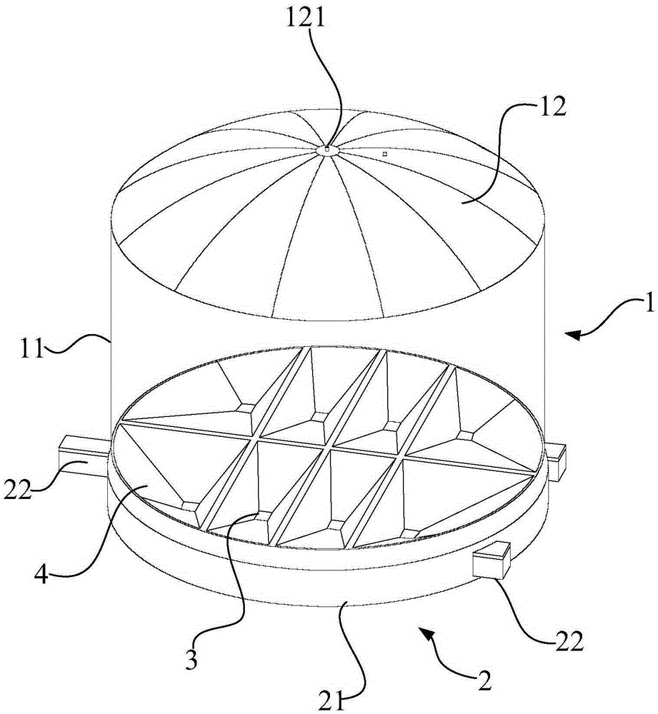
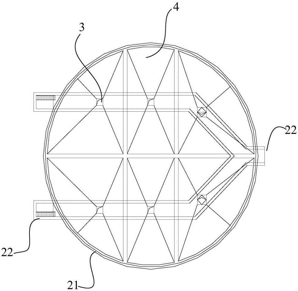
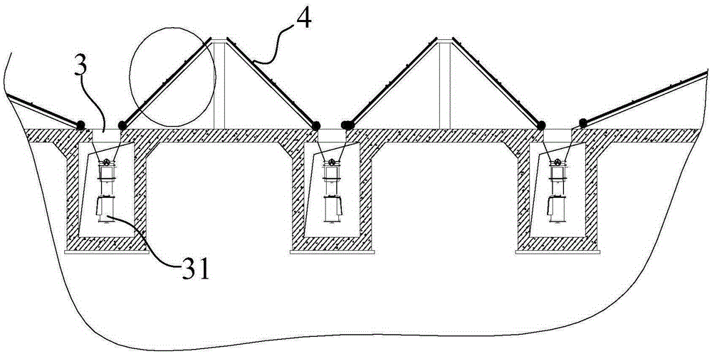
[0041] Example 1, such as figure 1 , figure 2 , image 3 As shown, this embodiment provides a multi-point multi-corridor energy-saving and environmentally friendly storage equipment, including a silo body 1 and an annular foundation 2 arranged under the silo body 1. The shape of the silo body 1 is cylindrical. The silo body 1 includes a cylindrical cylinder 11 and a silo roof 12 on the top of the cylinder 11. The shape of the silo roof 12 is a spherical shape, and a feed port 121 is arranged at the center of the silo roof 12. The entire silo The steel structure inside the main body 1 is kept stable, and the outlet 3 is evenly arranged at the bottom of the cylinder 11, and the outlet 3 is arranged at the bottom of the cylinder 11 in a row, and at least 2 rows are arranged at the bottom of the cylinder Outlet, at least 3 outlets are set for each outlet, and the outlets are arranged in parallel in a row. The main purpose of the row-like arrangement is to better cooperate with ...

Embodiment 2

[0048] Embodiment 2, this embodiment provides a method for discharging storage equipment with 6 discharge ports and 2 discharge corridors:

[0049] 1. First confirm whether the equipment other than the storage equipment is turned on, such as whether the power supply of the on-site equipment is connected, whether the manual gate valve at the unloading point at the bottom of the warehouse is in the open state, whether the elevator, chute, dust collector, and equipment used for the warehouse are opened. Whether the air source of the air compressor (such as the pulse valve of the dust collector, etc.) and other equipment have been operated. After confirmation, enter the operation of the gasification discharge system of the storage equipment.

[0050] 2. Opening, any one of the outlets (generally the outermost outlet is the opening point, that is, the outlet closest to the annular pouring edge) on the corresponding main air pipe (that is, above the first outlet corridor) Manual bu...

Embodiment 3

[0057] Embodiment 3, this embodiment provides a discharge method for storage equipment with 13 discharge ports and 3 discharge corridors, the difference from Embodiment 2 lies in the sequence of discharge, in this embodiment ,Such as Figure 7 As shown, first open the control valves No. 1, 8, and 9 of the discharge port, first open the pneumatic switch valve, and then open the electric flow control valve. To open the electric flow control valve, it is necessary to adjust the opening of the electric flow control valve. Open from small to large, monitor the discharge situation according to the current of the hoist motor, run the discharge stably for about 30 minutes, switch to discharge port No. 2, and close the discharge port No. 1 and No. 10 when switching between No. 7 and No. 10 No. 8 and No. 9 pneumatic switching valves, followed by closing the electric flow valve. After closing, open the pneumatic switching valves of No. 2, No. 7 and No. 10 feeding ports, and then open the...


PUM


Abstract

The invention belongs to the field of storage devices, and especially relates to a multi-point multi-gallery energy-saving environmental-protection storage device and a discharging method thereof. The multi-point multi-gallery energy-saving environmental-protection storage device comprises a silo body and an annular base under the silo body. The silo body comprises a barrel body and a silo top arranged on the top of the barrel body, discharging openings are uniformly arranged in the bottom of the barrel body in row, the discharging openings are arranged in parallel in row, the periphery of each discharging opening is provided with a material-guiding cone, any two adjacent material-guiding cones are arranged in a tangent manner, and the annular base comprises an annular pouring body used for fixing the silo body and discharging galleries which penetrate the annular pouring body and correspond to the discharging openings. According to the invention, the discharging openings are uniformly arranged in the bottom of the barrel body in row, the storage device is virtually divided into several storage units with a smaller diameter, at the same time, the material-guiding cones are combined with fluidization units, and therefore the multi-point multi-gallery energy-saving environmental-protection storage device does not have blind angles, and technical problems that a conventional device is not fully used, and the using effect is increasingly poor are solved.

Description

technical field [0001] The invention belongs to the field of storage equipment and relates to a steel silo, in particular to a multi-point multi-corridor energy-saving and environment-friendly storage equipment and a discharging method thereof. Background technique [0002] With the development of the national economy and the improvement of solid waste comprehensive utilization technology, the irreplaceable role of large steel silos has become more prominent. Steel silos have the outstanding advantages of large storage capacity, low investment, and fast construction. They have been widely used in the storage of bulk cement, slag powder, fly ash, alumina powder, grain and other powdery and granular materials. [0003] At present, the existing steel silos are mainly single-point discharge silos and multi-point discharge silos according to the discharge method. For example, the national intellectual property literature discloses the corresponding literature: a steel silo fluidi...

Claims


Application Information

Patent Timeline
IPC IPC(8): E04H7/22E04H7/30
CPCE04H7/22E04H7/30
Inventor 赵西军张保奎董喜龙
Owner SHANDONG YUANFENG CONSTR
Why Eureka
Try Eureka