Movable valve seat type spring loaded type relief valve

A direct-acting, moving valve seat technology, applied in the direction of functional valves, lifting valves, safety valves, etc., can solve the problems of incomplete compensation, cavitation wear, small pressure adjustment range, etc., and achieve pressure stability increase, Reduce impact force and erosion, avoid the effect of seat polarization

Inactive Publication Date: 2016-02-24
OCEAN UNIV OF CHINA
View PDF7 Cites 9 Cited by
  • Summary
  • Abstract
  • Description
  • Claims
  • Application Information

AI Technical Summary

Problems solved by technology

[0003] (1) For high-pressure or large-flow systems, the overflow valve and its components are large in size and weight, high in cost, and difficult to manufacture, and are not suitable for some transmission and control systems that have strict requirements on volume and weight, such as deep-sea operating systems , robot drive system, etc.
[0004] (2) The traditional direct-acting relief valve moves the spool relative to the valve seat. Due to the large effective pressure area of ​​the spool, the spring stiffness is large, resulting in a small pressure regulation range and low steady-state control accuracy.
[0005] (3) The hydraulic power in the traditional direct-acting relief valve is related to the valve core cone angle, flow rate, pressure and other parameters, which cannot be fully compensated, and the static and dynamic performance of the valve is poor

Method used


Image

  • Movable valve seat type spring loaded type relief valve
  • Movable valve seat type spring loaded type relief valve

Examples


Embodiment 1

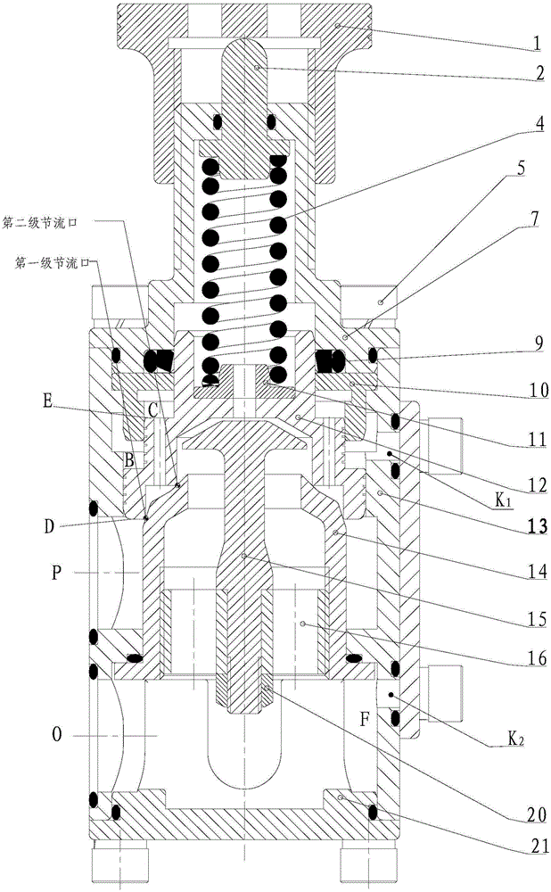
[0030] Example 1, such as figure 1 As shown, this embodiment discloses a movable valve seat type direct-acting overflow valve, which includes a valve body 13 with a cavity, and a water inlet P and a water outlet O on the valve body communicate with the above-mentioned cavity; the valve The valve core 14 and the valve seat 12 are arranged in the cavity of the body 13, the valve core 14 is fixed in the cavity in the valve body through the rear end cover 21, and the valve seat 12 is embedded in the cavity inside the sleeve 10 and the valve body 13, The sleeve 10 is pressed together with the front end cover 7; a spring 4 is arranged in the inner cavity of the front end cover 7, a spring ejector 2 is installed on the top of the spring 4, and a spring seat 11 is provided on the bottom of the spring 4, and one end of the spring 4 is in contact with the spring ejector 2 , the other end abuts against the spring seat 11, the spring seat 11 is installed in the axial through hole on the u...

Embodiment 2

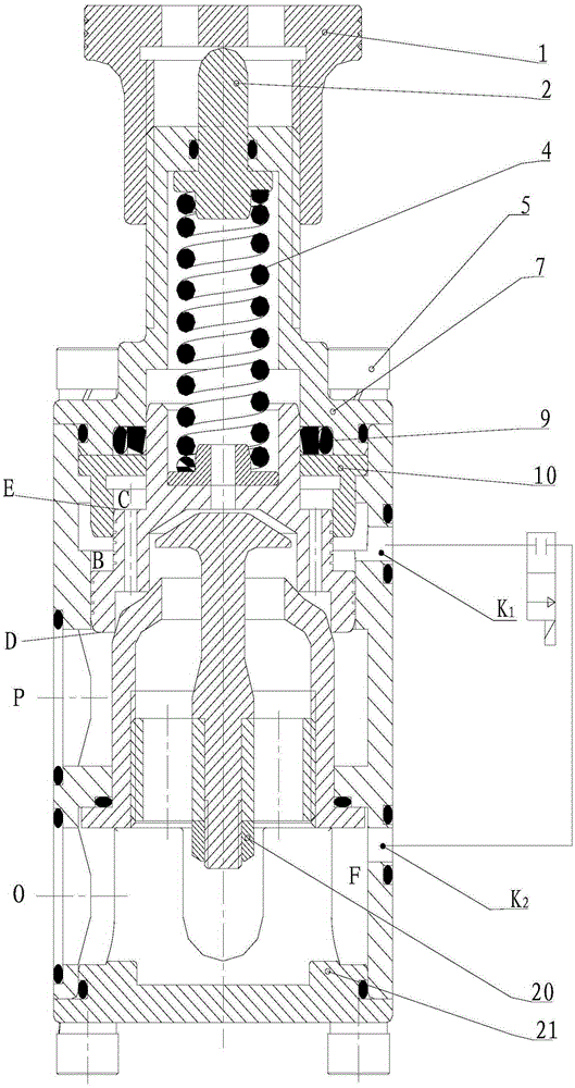
[0037] Example 2, such as figure 2 As shown, in this embodiment, on the basis of Embodiment 1, a control hole K1 is opened on the valve body to communicate with the space B between the first step of the valve seat and the sleeve; and the space F between the valve core and the rear end cover The connected control hole K2; the control holes K1 and K2 are respectively connected to the two ports of the two-position two-way electromagnetic reversing valve.

[0038] In this embodiment, if the two-position two-way electromagnetic reversing valve is opened, the fluid in space B can flow into space F through control holes K1 and K2, and space C loses pressure due to no fluid. With the pre-tightening force on the valve seat, the valve seat can move to the top, the overflow valve opens, and the fluid flows out of the overflow valve through the valve core and the water outlet. Due to the low spring stiffness, the fluid pressure only needs to overcome a small spring force to fully open the...


PUM


Abstract

The invention discloses a movable valve seat type spring loaded type relief valve. The movable valve seat type spring loaded type relief valve comprises a valve body provided with a cavity body. A water inlet and a water outlet communicated with the cavity body are formed in the valve body. A valve core and a valve seat are arranged inside the cavity body of the valve body. A spring is arranged inside a cavity of the interior of a front end cover. A spring ejection rod is installed at the top of the spring, and a spring base is arranged at the bottom of the spring. One end of the spring abuts against the spring ejection rod, and the other end of the spring abuts against the spring base. The valve seat comprises a two-stage step structure. The ascending end of the step structure is in clearance fit with the valve body and a sleeve. According to the movable valve seat type spring loaded type relief valve, a valve core king-rod structure is designed in the position of an injection inlet where fluid enters the valve core through the valve seat, so that the fluid power of the sprayed fluid is conducted to the valve core through a valve core king-rod, and the impact force and the corrosion to the valve seat by the fluid power are reduced; in addition, the step structure part of the valve seat makes contact with the two-stage conical surfaces of the valve core, so that a two-stage throttling valve port structure is formed between the valve seat and the valve core, and the effective partial pressure can be achieved.

Description

technical field [0001] The invention relates to the field of pressure control components, in particular to a movable seat type direct-acting overflow valve suitable for fluid transmission and control systems in this field. Background technique [0002] As a common pressure control component in fluid transmission and control systems, relief valves are used to ensure constant system pressure or limit the maximum working pressure of the system or actuators. The electromagnetic overflow valve (the traditional structure is a pilot-operated overflow valve and a two-position two-way electromagnetic reversing valve with a remote control port) can not only realize the function of the overflow valve, but also unload the pump. However, [0003] (1) For high-pressure or large-flow systems, the overflow valve and its components are large in size and weight, high in cost, and difficult to manufacture, and are not suitable for some transmission and control systems that have strict require...

Claims


Application Information

Patent Timeline
IPC IPC(8): F16K17/06F16K17/08F16K1/38F16K1/48
CPCF16K17/06F16K1/38F16K1/48F16K17/08
Inventor 杨友胜陆建辉聂松林吴进军冯辅周刘贵杰李洋王晓东
Owner OCEAN UNIV OF CHINA
Why Eureka
Try Eureka