Dynamic balance adjusting method of wavelength conversion device

A technology of a wavelength conversion device and an adjustment method, which is applied to components of lighting devices, lighting devices, optical elements for changing the spectral characteristics of emitted light, etc., and can solve problems such as defective products, shifting of the center of gravity, and complex implementation processes , to achieve the effect of simple operation and high precision

Inactive Publication Date: 2016-02-24
HISENSE
View PDF9 Cites 7 Cited by
  • Summary
  • Abstract
  • Description
  • Claims
  • Application Information

AI Technical Summary

Problems solved by technology

[0003] The structure of the fluorescent wheel is composed of a fluorescent wheel and a drive motor that drives the fluorescent wheel to rotate. Since the surface of the fluorescent wheel is partially coated with phosphor powder, and part of the non-phosphor powder area (such as the transmission area) is not coated with phosphor powder, resulting in uneven weight distribution. difference, center of gravity shift
When the fluorescent wheel rotates at high speed, it will cause the swing of the wheel body, which will affect the brightness and uniformity of the light output
[0004] At present, the dynamic balance adjustment of the fluorescent wheel is mainly realized by the following two methods. The first method is to form a metal weight layer on the fluorescent wheel. When the dynamic balance problem of the fluorescent wheel occurs, the metal weight layer on the fluorescent wheel is adjusted Cutting or punching holes on the metal weight layer to adjust the dynamic balance of the fluorescent wheel, but this method is complicated to implement, the force is not easy to control, and it is easy to cause damage to the fluorescent wheel, and the metal powder is easy to contaminate and scratch The surface of the fluorescent wheel leads to defective products; the second method is to pre-form grooves on the fluorescent wheel by de-weighting treatment. When the dynamic balance problem of the fluorescent wheel occurs, the effect of dynamic balance of the fluorescent wheel can be achieved by filling the groove with balancing substances , but when forming grooves in this way, the substrate structure of the fluorescent wheel needs to be changed, the controllable precision is low, and the implementation process is complicated

Method used


Image

  • Dynamic balance adjusting method of wavelength conversion device
  • Dynamic balance adjusting method of wavelength conversion device
  • Dynamic balance adjusting method of wavelength conversion device

Examples


Embodiment Construction

[0041] The following will clearly and completely describe the technical solutions in the embodiments of the present invention with reference to the accompanying drawings in the embodiments of the present invention. Obviously, the described embodiments are only some, not all, embodiments of the present invention. Based on the embodiments of the present invention, all other embodiments obtained by persons of ordinary skill in the art without making creative efforts belong to the protection scope of the present invention.

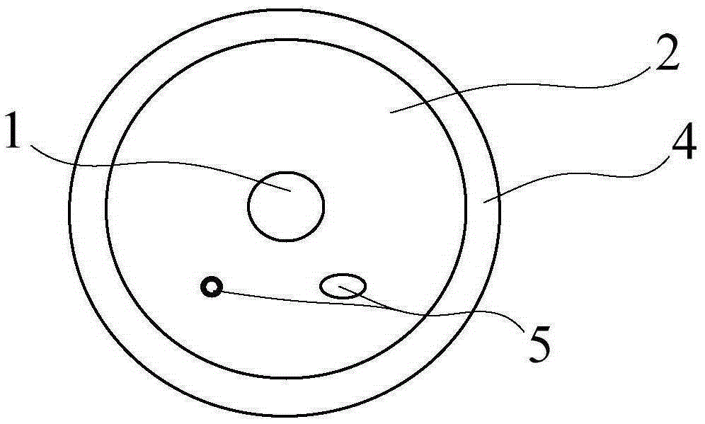
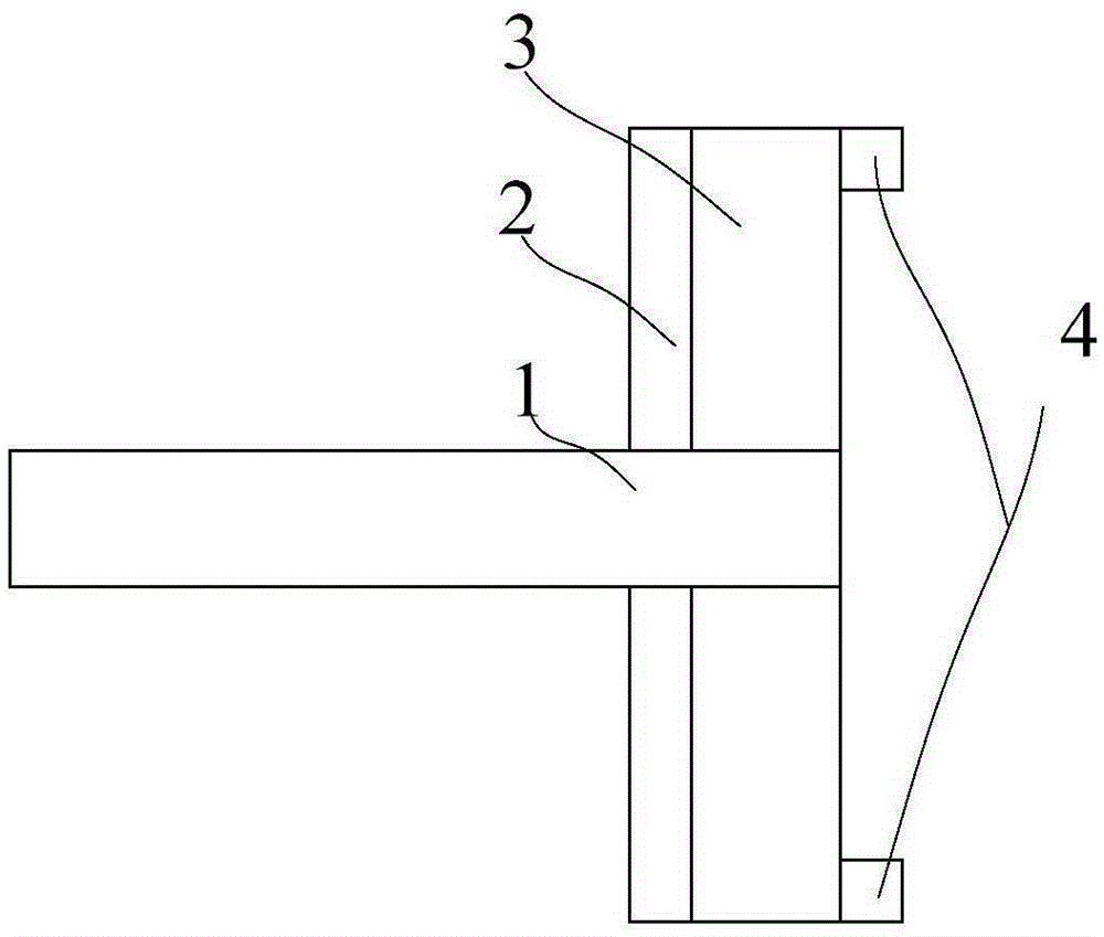
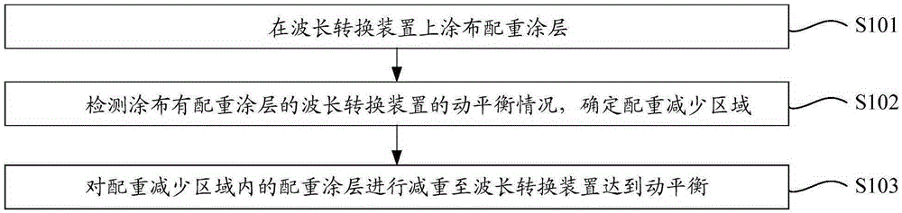
[0042] Such as figure 1 , image 3 as well as Figure 5 As shown, the present invention provides a dynamic balance adjustment method for a wavelength conversion device, including:

[0043] Step S101, forming a weight coating 2 on the wavelength conversion device;

[0044] Step S102, detecting the dynamic balance of the wavelength conversion device formed with the counterweight coating 2, and determining the counterweight adjustment area 5;

[0045] Step S1...


PUM


Abstract

The invention relates to the technical field of displaying, and discloses a dynamic balance adjusting method of a wavelength conversion device. The dynamic balance adjusting method of the wavelength conversion device comprises the following steps: a counterweight coating layer is formed on the wavelength conversion device; the dynamic balance condition of the wavelength conversion device havingthe counterweight coating layer formed thereon is detected to determine a counterweight adjusting area; and the thickness and the area of the counterweight coating layer in the counterweight adjusting area are adjusted until the wavelength conversion device reaches a dynamic balance. In the dynamic balance adjusting method of the wavelength conversion device, the adjustable counterweight coating layer of the wavelength conversion device is formed on the wavelength conversion device when the dynamic balance problem exists; the dynamic balance condition is detected to determine the counterweight adjusting area; the thickness and the area of the counterweight coating layer in the counterweight adjusting area are adjusted until the wavelength conversion device reaches a dynamic balance; and the thickness and the area of the counterweight coating layer are adjusted without damaging the wavelength conversion device, so that the operation is simple, and the precision is high.

Description

technical field [0001] The invention relates to the field of display technology, in particular to a dynamic balance adjustment method of a wavelength conversion device. Background technique [0002] In the laser display system, the wavelength conversion device is used for wavelength conversion. When the laser passes through the wavelength conversion device, it excites the fluorescent material to generate three primary colors of light with different wavelengths from the laser. At present, the commonly used wavelength conversion device is a fluorescent wheel structure. [0003] The structure of the fluorescent wheel is composed of a fluorescent wheel and a drive motor that drives the fluorescent wheel to rotate. Since the surface of the fluorescent wheel is partially coated with phosphor powder, and part of the non-phosphor powder area (such as the transmission area) is not coated with phosphor powder, resulting in uneven weight distribution. Difference, center of gravity shif...

Claims


Application Information

Patent Timeline
Patent Type & Authority Applications(China)
IPC IPC(8): F21V9/10C09D5/22C09D4/02C09D7/12F21V9/40
CPCC08K3/22C08K3/34C08K2003/2227C08K2003/2241C09D4/00C09D5/22C09D7/61F21V9/40
Inventor 邢哲
Owner HISENSE
Why Eureka
Try Eureka