Eureka AIR delivers breakthrough ideas for toughest innovation challenges, trusted by R&D personnel around the world.

Monitoring device and monitoring method for detecting downhole corrosion situation

A monitoring device and detection well technology, applied in the direction of measuring devices, weather resistance/light resistance/corrosion resistance, instruments, etc., can solve the problem that the corrosion and scaling of downhole piezometers and pipe strings cannot be monitored, and affect the normal production of oil and gas in oil wells , pipe strings and equipment safety hazards, etc., to ensure the normal operation of safe production, reduce economic and crude oil losses and crude oil pollution, and achieve significant economic and social benefits

Inactive Publication Date: 2016-02-24
CHINA PETROLEUM & CHEM CORP
View PDF9 Cites 10 Cited by
  • Summary
  • Abstract
  • Description
  • Claims
  • Application Information

AI Technical Summary

Problems solved by technology

[0003] However, there is no relevant corrosion monitoring device for downhole piezometers and pipe strings at present, so it is impossible to monitor the corrosion and scaling of downhole piezometers and pipe strings during oil well production. Obvious potential safety hazard. Once the downhole pressure gauge and pipe string are corroded, perforated or scaled to block equipment, it will seriously affect the normal production of oil and gas in the oil well, endanger personnel, cause safety accidents, and cause crude oil leakage and environmental pollution.

Method used


Image

  • Monitoring device and monitoring method for detecting downhole corrosion situation
  • Monitoring device and monitoring method for detecting downhole corrosion situation
  • Monitoring device and monitoring method for detecting downhole corrosion situation

Examples


Embodiment Construction

[0020] In order to better understand the purpose, structure and function of the present invention, the downhole corrosion monitoring device of the present invention will be further described in detail below in conjunction with the accompanying drawings.

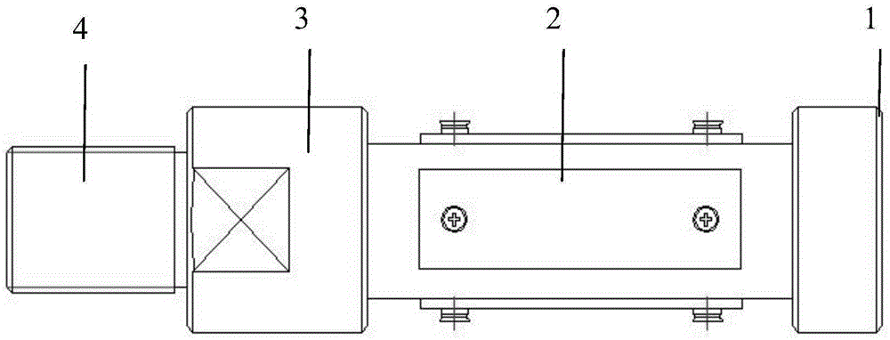
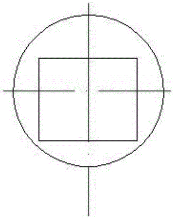
[0021] Such as figure 1 with figure 2 As shown, it is a monitoring device for detecting downhole corrosion of the present invention. The downhole corrosion monitoring device includes an integrally formed inverted cone joint 1, a hanging piece clip 2, a mounting part 3 and a threaded nipple 4, which are sequentially connected. Inverted cone joint 1 is used to orient the monitoring device in the downhole or at the bottom of the well. The threaded puppet 4 is connected with the downhole piezometer (not shown in the figure). The clip 2 is fixed on the outer wall of the installation part 3 to be fixedly connected with the downhole piezometer, and can go downhole with the downhole piezometer, completely immersed in the downhole f...


PUM


Abstract

The invention discloses a monitoring device and a monitoring method for detecting a downhole corrosion situation. The monitoring method comprises the following steps of recording data of a monitored hanging piece before entering a well; enabling the monitored hanging piece to descend into the well together with a downhole manometer by fixing the monitored hanging piece on a monitoring device; using the monitored hanging piece as an anode, and enabling the monitored hanging piece to be in contact with a fluid medium in a downhole pipe column to take an electrochemical reaction, so that the monitored hanging piece is subjected to corrosion, scaling and deposition scaling by the fluid medium; salvaging the monitored hanging piece and the monitoring device out of a wellhead together; counting data of the monitored hanging piece entered the well, and comparing the data with the data before entering the well so as to obtain the corrosion situation of a downhole device. According to the monitoring device and the monitoring method for detecting the downhole corrosion situation, disclosed by the invention, monitoring data can be obtained through weighing the monitored hanging piece and carrying out pitting corrosion measurement, the corrosion can be monitored in real time, and corrosion and scaling situations of devices such as the downhole manometer and the pipe column can be really reflected.

Description

technical field [0001] The invention relates to a downhole device, in particular to a monitoring device capable of detecting downhole corrosion. Background technique [0002] At present, downhole pressure gauges are commonly used in the oil and gas production process of single wells in oil fields. During the downhole pressure measurement process of oil wells, the downhole medium contains acidic and corrosive gases such as carbon dioxide and hydrogen sulfide. It also contains dissolved oxygen. Under high temperature and high pressure conditions, the combination of high water content in downhole fluid and highly corrosive gases dissolved in the medium will cause corrosion and scaling of downhole pressure gauges and downhole tubing strings. It is very necessary to monitor the corrosion degree of equipment and pipe strings near the meter. [0003] However, there is no relevant corrosion monitoring device for downhole piezometers and pipe strings at present, so it is impossible ...

Claims


Application Information

Patent Timeline
Patent Type & Authority Applications(China)
IPC IPC(8): G01N17/00
CPCG01N17/00
Inventor 张志宏张江江高淑红刘冀宁羊东明陈微秦飞
Owner CHINA PETROLEUM & CHEM CORP
Why Eureka
Eureka Blog
Learn More