
An automatic calibration device and method for an AC voltage divider

An automatic calibration and voltage divider technology, applied in the field of automatic calibration, can solve problems such as zero drift, frequency fluctuation, error, etc., and achieve the effect of AC voltage stability

Active Publication Date: 2018-01-05
STATE GRID CORP OF CHINA +3
View PDF5 Cites 0 Cited by
  • Summary
  • Abstract
  • Description
  • Claims
  • Application Information

AI Technical Summary

Problems solved by technology

The mains fluctuates greatly and the waveform distortion rate may be relatively high, and there is a certain fluctuation in frequency, which causes the readings of the standard metering equipment to jump all the time during calibration, and because of the influence of frequency and waveform distortion rate, There are also certain errors in the standard metering equipment used as a reference, and the mains plus voltage regulating transformer can only be calibrated against the 50Hz power frequency voltage divider; when the inverter power supply is used as the power supply of the intermediate frequency step-up transformer, the output The distortion rate of the waveform is high, and there are a large number of high-frequency interference components, among which the high-frequency interference will seriously affect the reading of the voltage divider, causing fluctuations and zero drift in the reading of the tested AC voltage divider

Method used


Image

  • An automatic calibration device and method for an AC voltage divider
  • An automatic calibration device and method for an AC voltage divider
  • An automatic calibration device and method for an AC voltage divider

Examples


Embodiment Construction

[0029] The technical solutions in the present invention will be clearly and completely described below in conjunction with the accompanying drawings in the present invention.

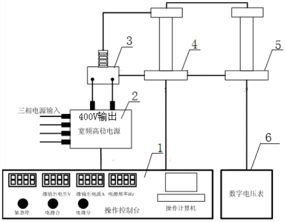
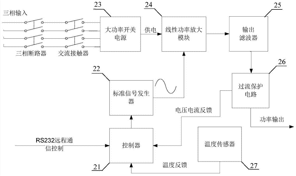
[0030] figure 1 Shown is the working principle diagram of the AC voltage divider automatic calibration device of the present invention, which is used for calibration of the AC voltage divider 5 to be tested, and the AC voltage divider automatic calibration device includes industrial computer systems 1 connected in sequence , broadband high-stable power supply 2, intermediate frequency step-up transformer 3, standard broadband voltage divider 4, digital voltmeter 6, the standard broadband voltage divider 4 is connected in parallel with the AC voltage divider 5 to be tested, the low voltage of the standard broadband voltage divider 4 The arm is connected with the industrial computer system 1, and is used to feed back the voltage of the high-voltage end of the standard broadband voltage divider 4 to the in...


PUM


Abstract

An automatic calibration device for an AC voltage divider, including an industrial computer system connected in sequence, a broadband high-stable power supply, an intermediate frequency step-up transformer, a standard broadband voltage divider, and the standard broadband voltage divider is used for parallel connection with the AC voltage divider to be tested . The industrial computer system is used to send control signals to control the frequency and amplitude of the output voltage of the broadband high-stable power supply according to the preset voltage detection point, to sample the voltage of the standard broadband voltage divider, and to adjust the standard broadband voltage divider by feedback automatic control The error between the voltage at the high-voltage end and the target set voltage, when the voltage at the high-voltage end of the standard broadband voltage divider reaches the preset voltage detection point, the boost will automatically stop; the intermediate frequency step-up transformer is used to boost the output voltage of the broadband high-stable power supply Then output to the standard broadband voltage divider and the AC voltage divider to be tested. The invention has stable output voltage, small waveform distortion rate, and small frequency deviation, which can avoid reading changes of resistive-capacitive voltage dividers caused by voltage quality problems. The entire detection and calibration process is fully automatic, and manual or mechanical voltage regulation can be avoided. Process operation error.

Description

technical field [0001] The invention relates to the technical field of automatic calibration of high-voltage metering equipment in a power system, in particular to an automatic calibration device and method for an AC voltage divider. Background technique [0002] AC voltage divider and other high-voltage metering equipment need to compare their readings with standard metering equipment during metering calibration. High voltage, the power capacity required at this time is very large, usually only the mains plus voltage regulator or inverter power supply can be used as the input power of the intermediate frequency step-up transformer to boost the voltage. The mains fluctuates greatly and the waveform distortion rate may be relatively high, and there is a certain fluctuation in frequency, which causes the readings of the standard metering equipment to jump all the time during calibration, and because of the influence of frequency and waveform distortion rate, There are also ce...

Claims


Application Information

Patent Timeline
Patent Type & Authority Patents(China)
IPC IPC(8): G01R35/02
Inventor 王永勤张露贺家慧童歆郑义刘黎王兰芳
Owner STATE GRID CORP OF CHINA
Learn More