Bistatic MIMO radar space maneuvering target tracking method

A mobile target tracking, bistatic technology, applied in the direction of reflection/re-radiation of radio waves, use of re-radiation, measurement devices, etc., can solve problems that do not involve target motion state estimation and prediction tracking

Inactive Publication Date: 2016-02-24
NO 63921 UNIT OF PLA
View PDF7 Cites 13 Cited by
  • Summary
  • Abstract
  • Description
  • Claims
  • Application Information

AI Technical Summary

Problems solved by technology

But this method does not involve target motion state estimation and prediction tracking

Method used


Image

  • Bistatic MIMO radar space maneuvering target tracking method
  • Bistatic MIMO radar space maneuvering target tracking method
  • Bistatic MIMO radar space maneuvering target tracking method

Examples


Embodiment Construction

[0090] The present invention will be described in detail below with reference to the accompanying drawings and embodiments.

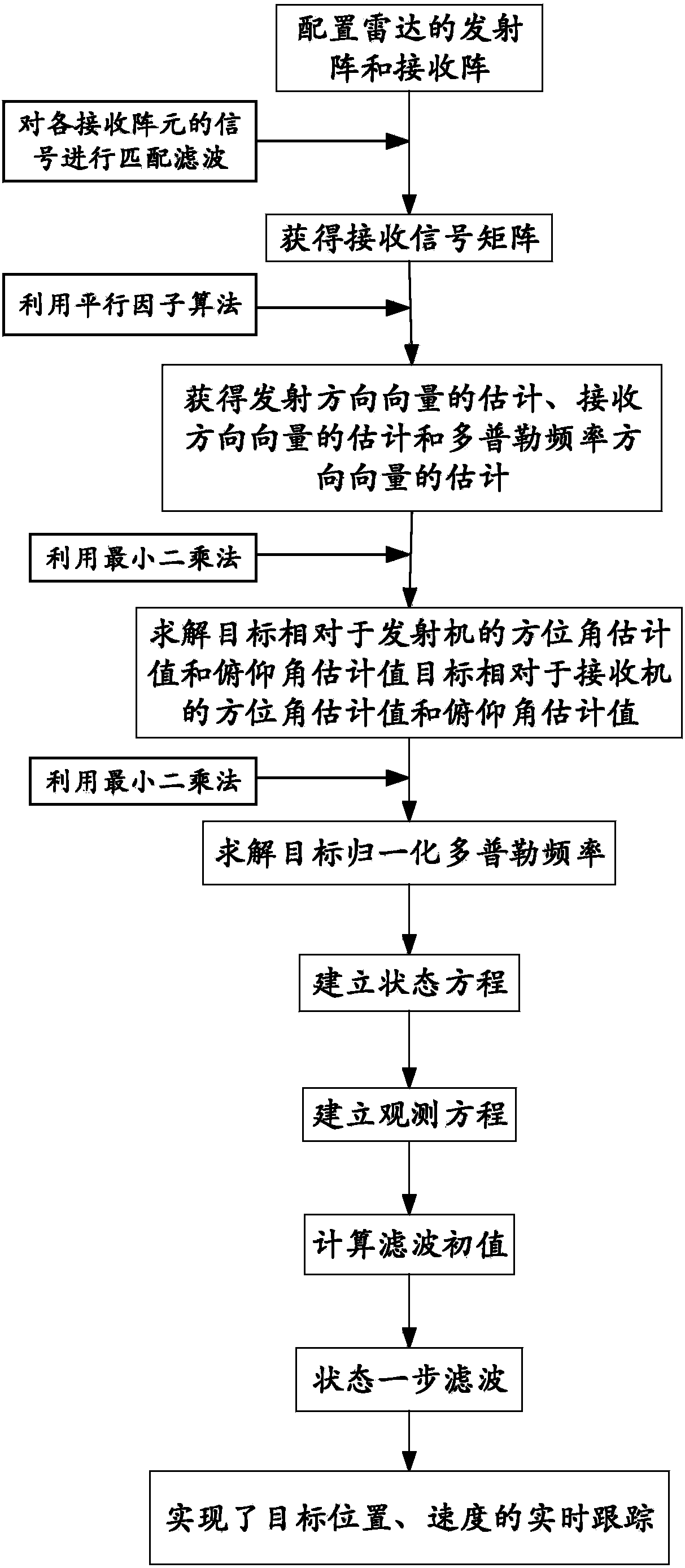
[0091] figure 1 For a kind of bistatic MIMO radar space maneuvering target tracking method of the present invention realizes flowchart, the concrete steps that realize the present invention are as follows:

[0092] Step 1, the transmitter of the bistatic MIMO radar is configured as a uniform circular array of M array elements, and the receiver is configured as a uniform circular array of N array elements, and the M array elements in the transmitter emit mutually orthogonal Waveform signal; where M represents the number of transmitter array elements, N represents the number of receiver array elements, and M and N are both natural numbers;

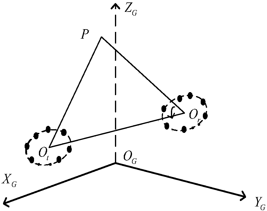
[0093] figure 2 It is a schematic diagram of the configuration of the bistatic MIMO radar of the present invention. The coordinate system adopts the earth-centered Cartesian coordinate system O G -X G Y G Z G ...


PUM


Abstract

The invention discloses a bistatic MIMO radar space maneuvering target tracking method capable of realizing accurate estimation and prediction of motion parameters such as the three-dimensional position and speed of space maneuvering targets. According to the method, a bistatic MIMO radar uniform circular array system is applied to space maneuvering target tracking, based on bistatic MIMO radar uniform circular array angle Doppler frequency estimation and the target state space, a measuring equation is established in a measuring right angle coordinate system for emitting and receiving uniform circular arrays according to a function relation between measuring elements and target motion state variables. A current statistics model applicable to maneuvering target tracking is employed to establish a state equation for describing the evolution of target motion parameters with time, the unscented Kalman filter algorithm applicable to nonlinear state filtering is employed to estimate the target motion parameters in real time, the target motion parameters can be predicted, and the tracking of the space maneuvering target is realized.

Description

technical field [0001] The invention belongs to the field of radar data processing, and in particular relates to a method for tracking a bistatic MIMO radar space maneuvering target. Background technique [0002] The bistatic radar is realized by adopting the separation structure of the receiver and the transmitter system. The main features of this structure are: the transmitter is placed at the rear, and the receiver is placed at the front, which can approach the target for covert detection, avoid the power loss caused by the two-way propagation of radar electromagnetic waves, and improve the signal-to-noise ratio of the target. The traditional bistatic meter-wave radar uses the angle and distance of the target relative to the receiving end to locate the space target. Because the receiver and the transmitter of the bistatic radar are difficult to meet the precise time synchronization, and its angular resolution and ranging accuracy are poor. Relatively low, resulting in lo...

Claims


Application Information

Patent Timeline
Patent Type & Authority Applications(China)
IPC IPC(8): G01S13/66
CPCG01S13/66
Inventor 徐安林梁小虎金胜王洋赵华周友德郭永强龙方
Owner NO 63921 UNIT OF PLA
Why Eureka
Try Eureka