Power transmission line wiring device

A wiring device and transmission line technology, which is applied in the direction of cable laying equipment, the layout of the use of reels/photosensitive drums, etc., can solve the problems of low wiring efficiency, winding of transmission lines, messy wiring of transmission lines, etc. To achieve the effect of simple structure

Inactive Publication Date: 2016-02-24
国网山东东明县供电公司
View PDF7 Cites 6 Cited by
  • Summary
  • Abstract
  • Description
  • Claims
  • Application Information

AI Technical Summary

Problems solved by technology

[0002] The transmission line is the most basic power transmission device in the power system. In the process of configuring the transmission line, it is usually necessary to configure multiple transmission lines at the same time. Since each transmission line is wound in a reel, when wiring, Each transmission line needs to be pulled out from the reel and stretched out to complete the wiring work of the transmission line. Since there is no dedicated wiring device, the existing method is to remove the transmission line from the reel one by one by the operator. Pull out the power lines and place the power lines on the ground. In this way, it is easy to cause uneven spacing between the power lines, and even the problem of entanglement of the power lines, which makes the wiring of the power lines very messy. Therefore, not only the distribution The efficiency of the transmission line is low, and it will also lead to technical problems in the connection of the transmission line in the follow-up work

Method used


Image

  • Power transmission line wiring device
  • Power transmission line wiring device
  • Power transmission line wiring device

Examples


Embodiment Construction

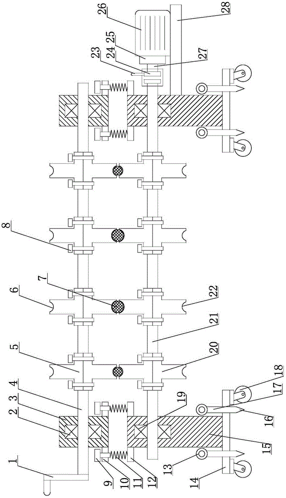
[0015] like figure 1 As shown, the transmission line distribution device of the present invention includes an upper rotating shaft 4 and a lower rotating shaft 21, the upper rotating shaft 4 and the lower rotating shaft 21 are parallel to each other and are parallel to the horizontal plane, and the left and right ends of the upper rotating shaft 4 are provided with a Bearing sleeve 3, an upper bearing 2 is arranged inside the bearing sleeve 3, the left and right ends of the upper rotating shaft 4 are respectively inserted into the upper bearing 2, and the left and right ends of the lower rotating shaft 21 are provided with a supporting frame 15. A lower bearing 19 is provided in the support frame 15, and the left and right ends of the lower rotating shaft 21 are respectively inserted into the lower bearing 19, and several upper driving wheels 5 are fixed on the upper rotating shaft 4. Several lower driving wheels 20 are fixed on the lower rotating shaft 21, and the upper drivi...


PUM


Abstract

The invention discloses a power transmission line wiring device which comprises an upper rotation shaft and a lower rotation shaft. The lower rotation shaft is fixedly provided with a plurality of lower driving wheels. Upper driving wheels are in one-to-one correspondence with the lower driving wheels. The circumference direction of each upper driving wheel is provided with an upper driving groove. The circumference direction of each lower driving wheel is provided with a lower driving groove. The bottom surface of the upper driving groove and the bottom surface of the lower driving groove are arc surfaces. The upper driving groove and the lower driving groove of the corresponding upper driving wheel and the lower driving wheel are same in size. The wiring device also comprises a motor plate. The motor plate is fixedly provided with a motor. The motor is equipped with a speed reducer. The speed reducer is provided with a main shaft. A clutch is arranged between the main shaft and the lower rotation shaft. The clutch is provided with a clutch lever. The beneficial effects are that 1) the power transmission line wiring device is simple in structure; 2) the wiring device can carry out wiring on a plurality of same-diameter power transmission lines, and can also carry out wiring on a plurality of different-diameter power transmission lines; and 3) the wiring device not only has a manual wiring function, but also has an automatic wiring function.

Description

technical field [0001] The invention relates to a power installation device, in particular to a transmission line distribution device. Background technique [0002] The transmission line is the most basic power transmission device in the power system. In the process of configuring the transmission line, it is usually necessary to configure multiple transmission lines at the same time. Since each transmission line is wound in a reel, when wiring, Each transmission line needs to be pulled out from the reel and stretched out to complete the wiring work of the transmission line. Since there is no dedicated wiring device, the existing method is to remove the transmission line from the reel one by one by the operator. Pull out the power lines and place the power lines on the ground. In this way, it is easy to cause uneven spacing between the power lines, and even the problem of entanglement of the power lines, which makes the wiring of the power lines very messy. Therefore, not on...

Claims


Application Information

Patent Timeline
Patent Type & Authority Applications(China)
IPC IPC(8): H02G1/06H02G11/02
Inventor 谷俊峰毕文俭王兴华文万众刘志军张新洪陈兆领海朝忠李东生王飞牛建里
Owner 国网山东东明县供电公司
Why Eureka
Try Eureka