Laminated electric heating auto glass with transverse transition zones

A technology for electrically heating glass and transition zones, applied in windshields, transparent/reflective heating devices, vehicle components, etc., can solve problems such as affecting the heating effect, the semi-resistance zone can only be heated, and the film layer can only be slightly heated, etc. To achieve the effect of improving the heating effect

Active Publication Date: 2016-02-24
FUJIAN WANDA AUTOMOBILE GLASS IND
View PDF9 Cites 1 Cited by
  • Summary
  • Abstract
  • Description
  • Claims
  • Application Information

AI Technical Summary

Problems solved by technology

However, the semi-resistive area constructed by this method is directly connected to the upper and lower busbars through multiple transition bars, causing the current in the semi-resistive area to pass directly through the transition bar. Therefore, the construction of a semi-resistive area can only achieve line heating, but cannot achieve heating of the entire area. heating effect
[0013] The existing conventional technology builds a semi-resistive area connected to the upper or lower bus bar. The semi-resistive area is composed of multiple sets of transition bars. The transition bar is directly connected to the upper or lower bus bar. This method allows the current to flow into the conductive film after passing through the transition bar. In the layer, it plays the role of heating, but this method will make the semi-resistance area built can only heat the transition strip, or the film layer can only be slightly heated, and it is difficult to obtain sufficient deicing and defrosting effects when the glass height is large

Method used


Image

  • Laminated electric heating auto glass with transverse transition zones
  • Laminated electric heating auto glass with transverse transition zones
  • Laminated electric heating auto glass with transverse transition zones

Examples


Embodiment 1

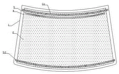
[0043] Such as figure 1 As shown, the present invention includes a glass substrate 1, and an electrically heated conductive film assembly is plated on the glass substrate 1. The electrically heated conductive film assembly is composed of a conductive film layer 2, a first bus bar 3.1 and a second bus bar 3.2. The film layer 2 is plated on the glass substrate 1, the first bus bar 3.1 and the second bus bar 3.2 are respectively connected to the upper and lower ends of the conductive film 2, and the first bus bar 3.1 and the second bus bar 3.2 are respectively arranged on the glass substrate 1. The upper edge and the lower edge; a transition area 4 is provided on the conductive film layer 2 of the glass substrate 1, and the transition area 4 is composed of several conductive transition strips 5, and the several conductive transition strips 5 are printed on the conductive film layer by silver paste 2 and / or a metal foil strip, the transition zone 4 is close to the first bus bar 3...

Embodiment 2

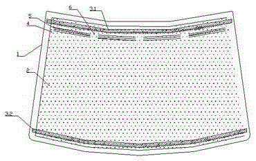
[0059] figure 2 gives something like figure 1 The structure of each group of conductive transition strips 5 is provided with gaps 6, and the gaps 6 are in the same position.

Embodiment 3

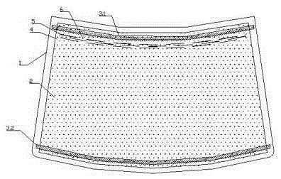
[0061] image 3 gives something like figure 1 structure, wherein the gaps 6 of the conductive transition strips 5 are arranged alternately.


PUM

PropertyMeasurementUnit
widthaaaaaaaaaa

Abstract

The invention provides laminated electric heating auto glass with transverse transition zones. The transition zones are arranged on a conductive film layer (2) of a glass substrate (1) and composed of a plurality of conductive transition strips (5); each conductive transition strip comprises a silver paste strip and/or a metal foil strip, wherein silver paste is printed on the conductive film layer (2) and then dried to form the silver paste strips; the transition zones 4 are close to a first bus (3.1) and/or second bus (3.2); the conductive transition strips (5) are not in direct contact with the first bus (3.1) and the second bus (3.2). The laminated electric heating auto glass has the advantages that the transition zones are constructed without affecting the normal vision field of a main vision area; due to construction of the transition zones, the heating effect of the main vision area can be improved and the transition zones also can take a heating effect.

Description

technical field [0001] The invention relates to the technical field of electric heating of automobile glass, in particular to an automobile laminated electric heating glass with a horizontal line transition area. Background technique [0002] At present, there are roughly two heating methods on the market for the front glass of automobiles: [0003] 1. Print the silver-containing conductive solution (hereinafter referred to as "silver paste") on the glass by screen printing and then bake it. Use welding or pasting to make electrical connections, and connect the positive and negative poles of the power supply to allow the current to pass through. To achieve the effect of heating. It is known that it has been widely used in the rear windshield of automobiles, but for the front windshield, this method is only suitable for heating the wiper area, because the national standard stipulates that there are no things other than heating wires in the main viewing area, so this method ...

Claims


Application Information

Patent Timeline
Patent Type & Authority Applications(China)
IPC IPC(8): H05B3/84B60J1/00
Inventor 王科研吴礼德尚贵才毛胤达商太友
Owner FUJIAN WANDA AUTOMOBILE GLASS IND
Why Eureka
Try Eureka