Limiting device for cage rolling machine

A technology of limiting device and rolling cage, applied in auxiliary devices, auxiliary welding equipment, welding/cutting auxiliary equipment, etc., can solve the problems of reduced construction efficiency, inability to guarantee steel bars, low construction efficiency, etc., to improve production quality and production. Efficiency, improve production and construction efficiency, the effect of strong overall stability

Inactive Publication Date: 2016-03-02
孙鸿雁
View PDF18 Cites 4 Cited by
  • Summary
  • Abstract
  • Description
  • Claims
  • Application Information

AI Technical Summary

Problems solved by technology

[0002] At present, in pile foundation construction, manual processing of steel cages is generally used, which is relatively low in construction efficiency and difficult to control the processing quality of steel cages. In order to ensure the processing quality and improve the processing efficiency of steel cages, some projects have gradually begun to use rolling cage machines to process steel bars cage
In the actual welding of the rolling cage machine, the control of the linear displacement of the main reinforcement in the reinforcement cage is mainly through the method of manual visual inspection to confirm that the end of the main reinforcement in the reinforcement cage is at the required end face position; the

Method used


Image

  • Limiting device for cage rolling machine
  • Limiting device for cage rolling machine
  • Limiting device for cage rolling machine

Examples


Embodiment Construction

[0030] The present invention is described in further detail now in conjunction with accompanying drawing. These drawings are all simplified schematic diagrams, which only illustrate the basic structure of the present invention in a schematic manner, so they only show the configurations related to the present invention.

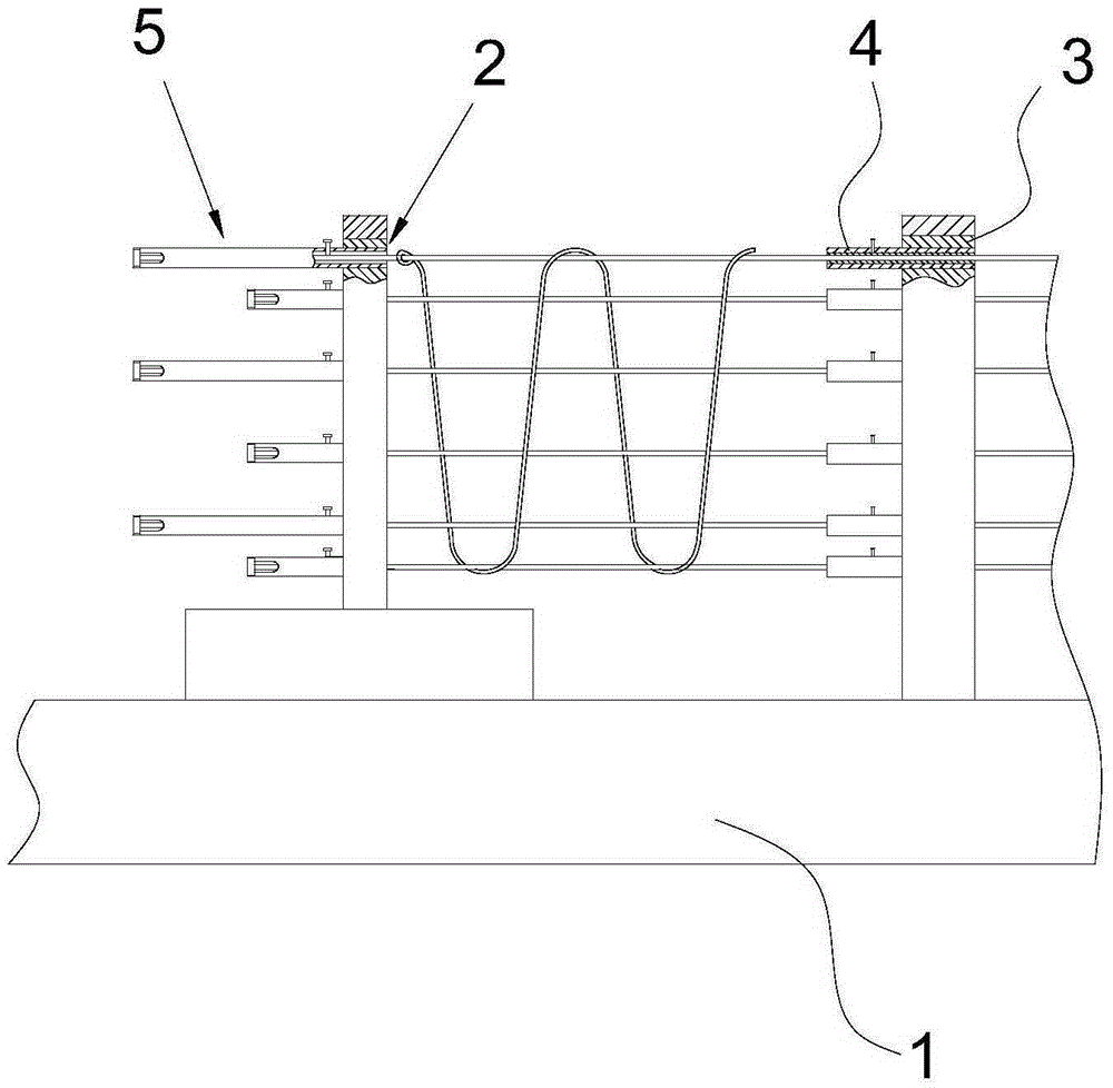
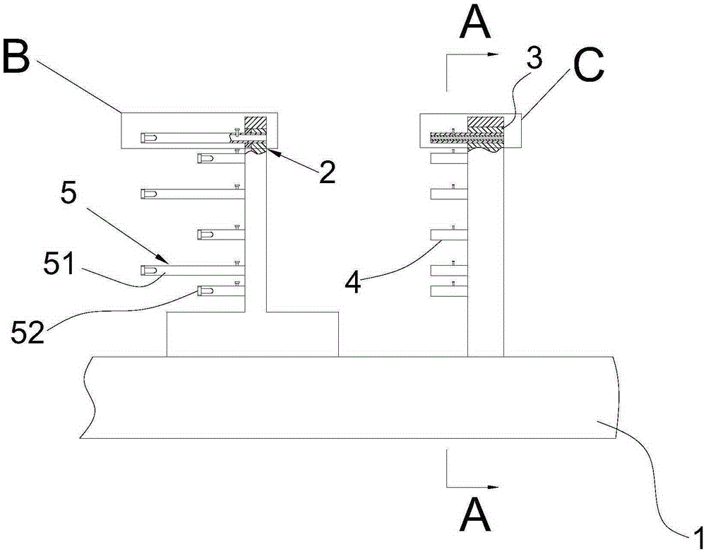
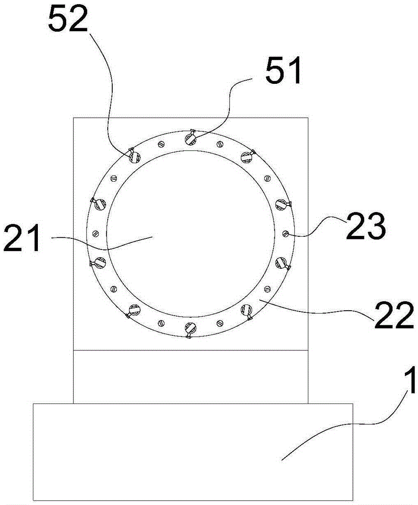
[0031] Such as Figure 1-Figure 11 Shown is a limiting device for a rolling cage machine of the present invention, the rolling cage machine includes a track platform 1, a moving turntable 2 and a positioning turntable 3, the moving turntable 2 is slidably connected to the track platform 1, and the positioning turntable 3 is fixedly connected On the track platform 1, the limit device used for the rolling cage machine includes an outer cylinder 4 and an end cylinder 5. A plurality of end cylinders 5 are uniformly distributed on the circumference and run through the moving turntable 2, and a plurality of outer cylinders 4 are uniformly distributed on the circumfe...


PUM


Abstract

The invention relates to the field of tool equipment, in particular to a limiting device for a cage rolling machine. The cage rolling machine comprises a rail platform, a movable rotary disc and a positioning rotary disc. The movable rotary disc is connected to the rail platform in a sliding mode, and the positioning rotary disc is fixedly connected to the rail platform. The limiting device for the cage rolling machine comprises outer barrels and end barrels. The end barrels are evenly distributed circumferentially and penetrate through the movable rotary disc, and the outer barrels are evenly distributed circumferentially and penetrate through the positioning rotary disc. The outer barrels correspond to the end barrels one to one. The ends, away from the outer barrels, of the end barrels are provided with end covers, and first limiting bolts penetrate through the barrel walls of the end barrels. The limiting device has the following advantages that operation is easy; main reinforcements are not likely to loose; steel reinforcement cages which are good in stability and high in strength can be manufactured; vibration can be lowered through inner barrels, and welding quality is guaranteed; it is guaranteed that the reserved sections of the steel reinforcement cages are located in the same section through the end covers, a pre-assembling procedure is omitted, the limiting device can be directly conveyed to a site to be connected in a non-break-joint mode, labor cost is greatly reduced, and construction efficiency is improved.

Description

technical field [0001] The invention relates to the field of tooling equipment, in particular to a limiting device for a rolling cage machine. Background technique [0002] At present, in pile foundation construction, manual processing of steel cages is generally used, which is relatively low in construction efficiency and difficult to control the processing quality of steel cages. In order to ensure the processing quality and improve the processing efficiency of steel cages, some projects have gradually begun to use rolling cage machines to process steel bars cage. In the actual welding of the rolling cage machine, the control of the linear displacement of the main reinforcement in the reinforcement cage is mainly through the method of manual visual inspection to confirm that the end of the main reinforcement in the reinforcement cage is at the required end face position; the reinforcement cage produced by this visual inspection method All the steel bars cannot be guarante...

Claims


Application Information

Patent Timeline
IPC IPC(8): B23K37/04B23K37/047
CPCB23K37/0426B23K37/047
Inventor 孙鸿雁
Owner 孙鸿雁
Why Eureka
Try Eureka