

Full-automatic part sorting and conveying system
A conveying system, fully automatic technology, applied in sorting, metal processing, metal processing equipment, etc., can solve the problems of low sorting efficiency, unfavorable automatic flow operation, complex structure, etc., to improve work efficiency and accuracy, The effect of promoting automatic flow operation and reducing labor intensity
- Summary
- Abstract
- Description
- Claims
- Application Information
AI Technical Summary
Problems solved by technology
Method used
Image

Examples
Embodiment Construction
[0030] In order to facilitate the understanding of those skilled in the art, the present invention will be further described below in conjunction with the embodiments and accompanying drawings, and the contents mentioned in the embodiments are not intended to limit the present invention. The present invention will be described in detail below in conjunction with the accompanying drawings.
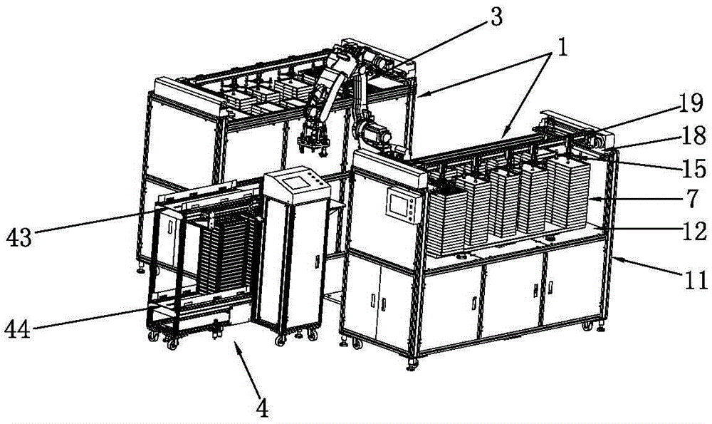
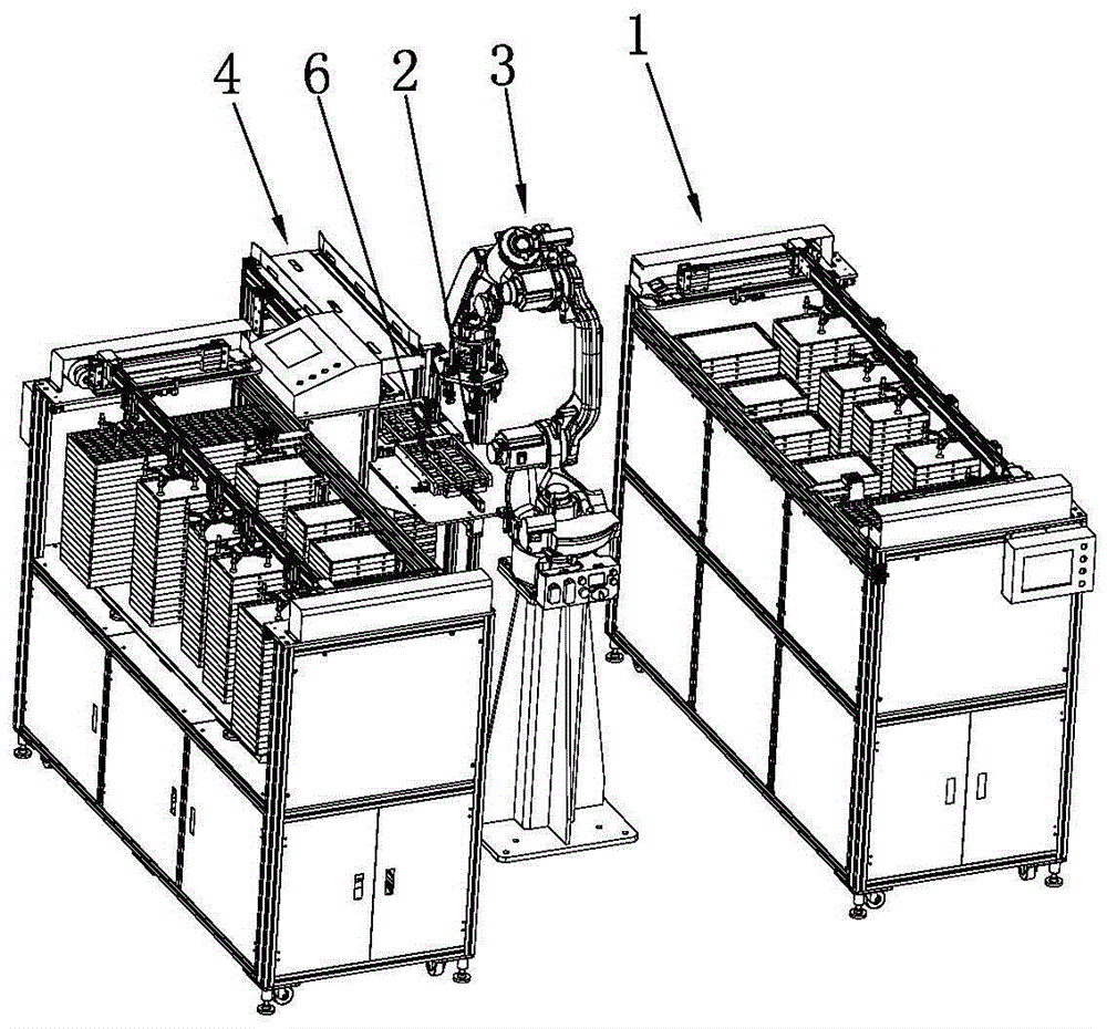
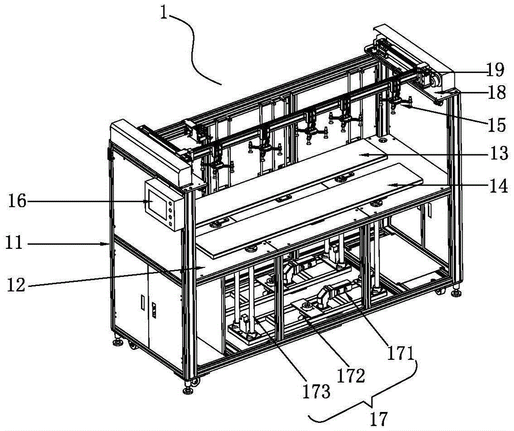
[0031] A fully automatic sorting and conveying system for parts provided by the present invention includes an automatic feeding device 1 for sorting and transporting parts to the adsorption and grabbing station; a material receiving workbench 2 for supporting a The batching tray 6 of the cavity, the batching tray 6 completes the distribution of parts on the material receiving workbench; the parts grabbing robot arm 3 moves back and forth between the automatic feeding device 1 and the material receiving workbench 2, from the adsorption and grabbing station Put the parts into the charging cav...
PUM
 Abstract
Description
Claims
Application Information