Multi-rotor unmanned aerial vehicle
A multi-rotor unmanned and flying equipment technology, applied in the field of multi-rotor unmanned flying equipment, can solve the problems of cumbersome installation and disassembly work and affect the working efficiency of staff, and achieve the effect of portable operation efficiency
- Summary
- Abstract
- Description
- Claims
- Application Information
AI Technical Summary
Problems solved by technology
Method used
Image
Examples
Embodiment 1
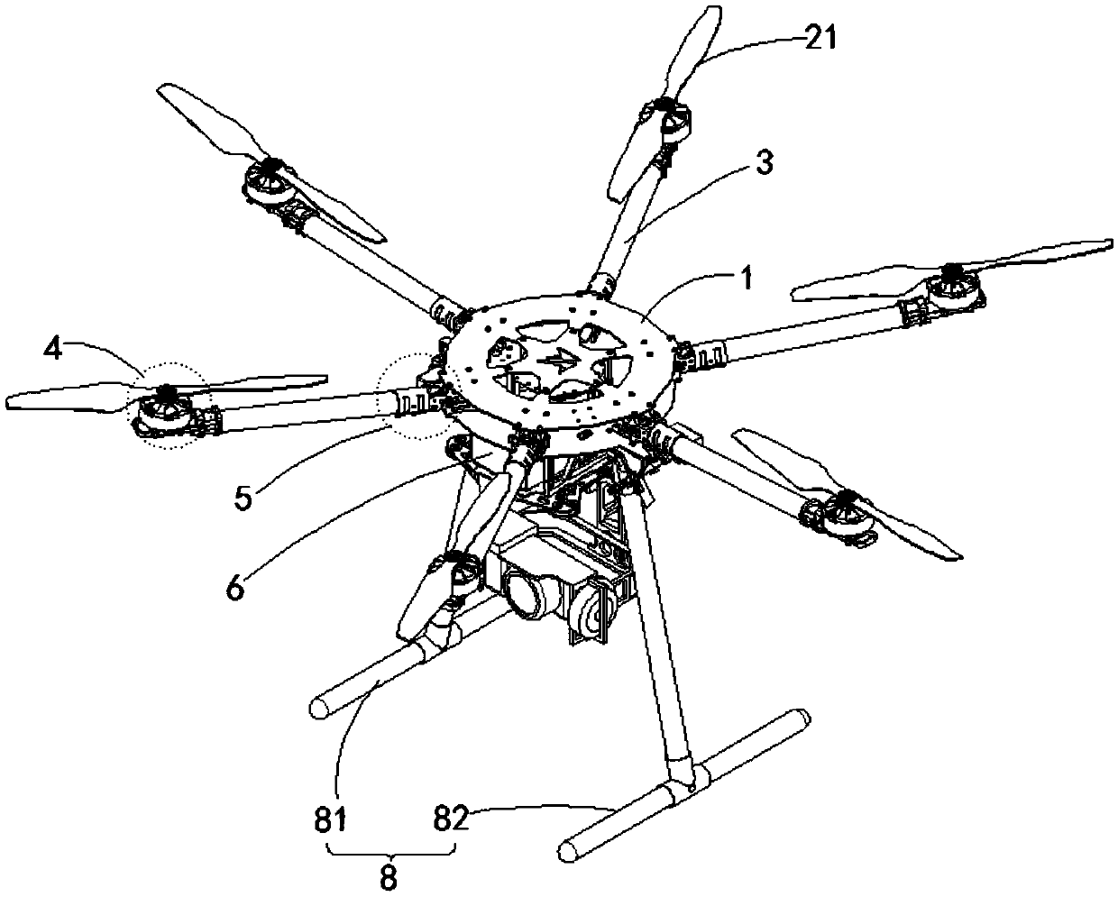
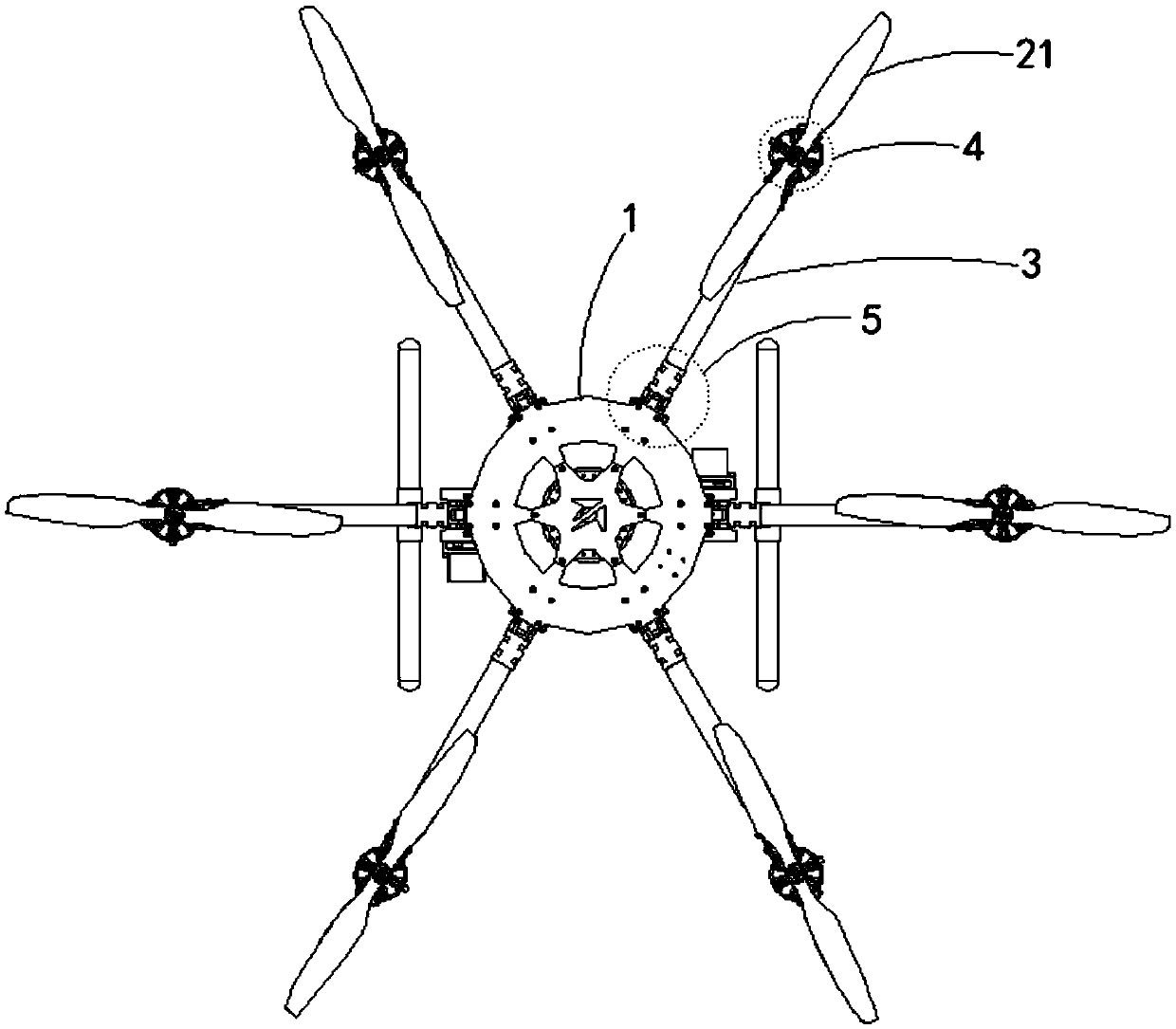
[0034] Specifically, see Figure 1-2 A multi-rotor unmanned aerial vehicle provided by Embodiment 1 of the present invention at least includes: a fuselage 1, at least four first rotors 2, rotor shafts 3 having the same number as the first rotors 21, and the first Rotary wings 21 have the same number of rotating connectors 4 , the same number of folding components 5 as the first rotor 21 , sliding components 6 and brackets 8 for placing batteries.
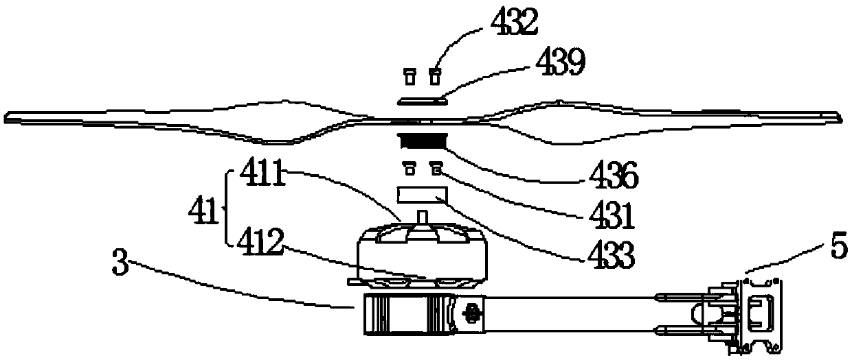
[0035] Wherein, one first rotor 21 is detachably connected to one rotor shaft 3 through one rotary connection 4 . please if Figure 3-4 As shown, the rotary connector 4 at least includes: a first motor 41 and a first dismounting thread group 43 . The first motor 41 is used to drive the first rotor 21 to rotate to drive the fuselage 1 to fly. The first motor 41 includes a first surface 411 and a second surface 412 . In the embodiment of the present invention, it can be as image 3 As shown, the first surface 411 can be understoo...
Embodiment 2
[0062] Take the twelve-rotor unmanned aerial vehicle as embodiment two of the present invention, because Figure 1-2 The six-rotor unmanned aerial devices shown all use a single-blade single-axis, that is, each rotating shaft 3 is equipped with a first motor 41 and a first rotor 21 . when Figure 1-2 As shown in the six-rotor unmanned aerial vehicle, when each of the rotating shafts 3 is equipped with two motors and two rotors, that is, both propellers are coaxial (two rotors share one rotor shaft 3), that is, twelve rotors are formed. Unmanned aerial equipment. Can be like Figure 11 shown.
[0063] At this time, one end of the rotor shaft 3 used to connect to the fuselage 1 is used as the connection end 32 , and is rotatably connected to the fuselage 1 through the folding assembly 5 . One end of the rotor shaft 3 used to connect the rotor serves as the coaxial end 21 , and the coaxial end 31 may include a first end surface 311 (upper end surface), a second end surface 31...
PUM
 Abstract
Description
Claims
Application Information
 - R&D
- Intellectual Property
- Life Sciences
- Materials
- Tech Scout
- Unparalleled Data Quality
- Higher Quality Content
- 60% Fewer Hallucinations
Browse by: Latest US Patents, China's latest patents, Technical Efficacy Thesaurus, Application Domain, Technology Topic, Popular Technical Reports.
© 2025 PatSnap. All rights reserved.Legal|Privacy policy|Modern Slavery Act Transparency Statement|Sitemap|About US| Contact US: help@patsnap.com


