Method for improving economical efficiency of engineering mechanical fuel

A technology of fuel economy and construction machinery, applied in mechanical equipment, engine control, fuel injection control, etc., can solve problems such as unsatisfactory fuel economy, reduced fuel economy, engine flameout, etc., to improve fuel economy and reduce Improve fuel consumption and combustion sufficiency

Inactive Publication Date: 2016-03-02
WEICHAI POWER CO LTD
View PDF6 Cites 3 Cited by
  • Summary
  • Abstract
  • Description
  • Claims
  • Application Information

AI Technical Summary

Problems solved by technology

In practice, the idling speed setting value of construction machinery is often higher than that of locomotives. The reason is that most construction machinery works at idling speed. When the idling speed is too low, the external output power may cause the engine to stall.
[0007] However, when the crane is performing hoisting operations, the total power of the engine will inevitably increase, and the corresponding fuel injection volume will increase accordingly; while the speed setting value remains unchanged at this time, the corresponding intake air volume will also remain unchanged. Although the speed setting value is higher than the corresponding idle speed of ordinary locomotives, it still cannot meet the requirements of fuel economy, resulting in a decrease in fuel economy
That is to say, during the lifting operation, the universal characteristic area corresponding to the speed maintained at the set value is not the economic area, and the fuel consumption at this time is relatively high
At the same time, during the unloading operation, the engine does not need to do external work, but at this time it is still necessary to maintain the engine speed at a set value, which is higher than the idle speed of ordinary locomotives, and the corresponding fuel consumption is relatively high

Method used


Image

  • Method for improving economical efficiency of engineering mechanical fuel
  • Method for improving economical efficiency of engineering mechanical fuel

Examples


Embodiment Construction

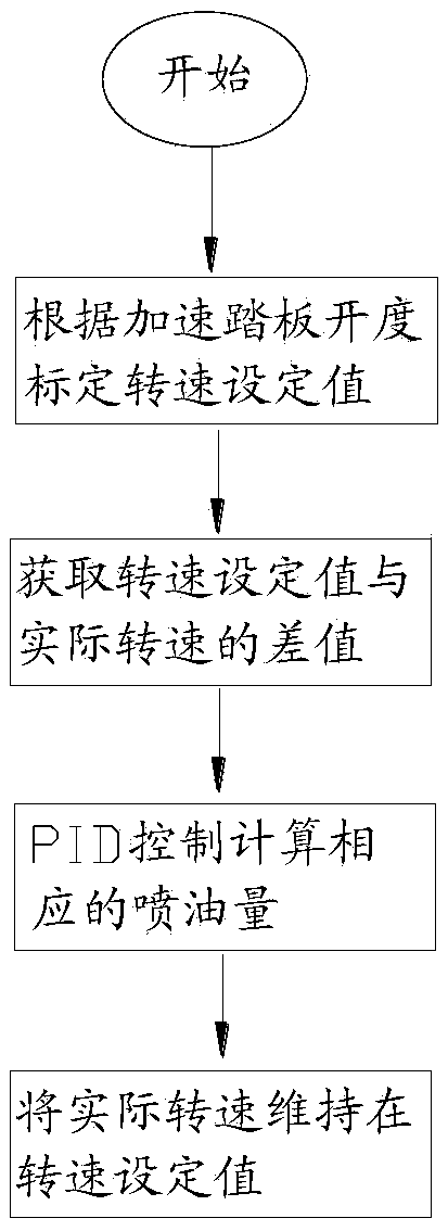
[0024] The core of the present invention is to provide a method for improving the fuel economy of construction machinery, so that the working condition of the engine can be adjusted to the universal characteristic economic zone without changing the engine configuration, and the fuel economy can be improved on the premise of satisfying the output power sex.

[0025] The material distributing device of the present invention will be described in detail below in conjunction with the accompanying drawings, so that those skilled in the art can accurately understand the technical solution of the present invention.

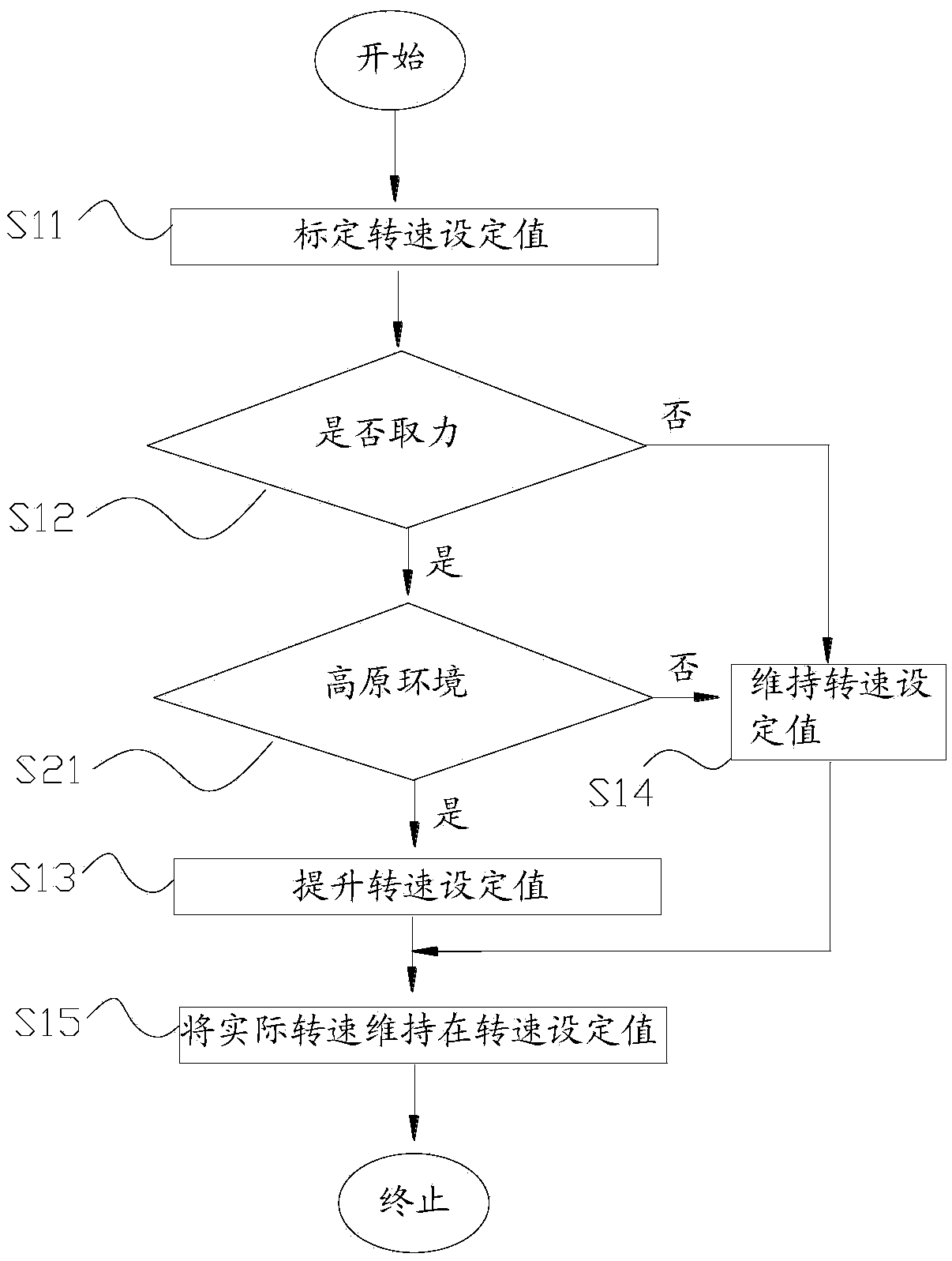
[0026] like figure 2 As shown, the present invention provides a kind of method that improves construction machine fuel economy, comprises the following steps:

[0027] S11: Calibrate the speed setting value according to the accelerator pedal opening, the universal characteristic area corresponding to the speed setting value is in the fuel economy zone, usually the idle ...


PUM


Abstract

The invention provides a method for improving the economical efficiency of engineering mechanical fuel. Under the condition that the configuration of an engine is not changed, the working condition of the engine is adjusted to a universal characteristic economic region, and the economical efficiency of the fuel is improved on the premise that the requirement for the output power is met. The method includes the steps that 11, whether force needs to be obtained or not is judged, if yes, the step 21 is executed, and if not, the step 31 is executed; 21, a rotation speed set value is increased; 31, the rotation speed set value is maintained or reduced to an idling set value of a fuel economic region; and 41, the actual rotation speed is maintained at the rotation speed set value. When force needs to be obtained, the rotation speed set value is increased so as to increase the air inflow, and therefore the combustion sufficiency of the fuel is improved; and when force is not needed, the rotation speed set value is maintained or reduced to the idling set value of the economic region, and fuel consumption is reduced. Therefore, the rotation speed set value is calibrated differentially according to the condition whether force is obtained or not, so that the rotation speed set value is better matched with the working condition, the fuel can be burnt sufficiently under various working conditions, and the economical efficiency of the fuel is improved.

Description

technical field [0001] The invention relates to the technical field of construction machinery, in particular to a method for improving the fuel economy of construction machinery. Background technique [0002] In the prior art, PID is usually used to control the rotational speed of the engine. The so-called PID control refers to an automatic control method that makes the controlled object quickly reach the target set value by setting the target value of the controlled object and the current value of the controlled object, and using proportional, integral, and differential methods. In the following, a crane is taken as an example for specific description. [0003] Please refer to figure 1 , figure 1 It is a schematic flow chart of PID control in the prior art. [0004] The working mode of the existing crane is the full-range speed regulation mode. In this mode, the corresponding speed setting value is calculated according to the pedal opening, and the speed setting value c...

Claims


Application Information

Patent Timeline
Patent Type & Authority Applications(China)
IPC IPC(8): F02D41/08
CPCF02D31/008
Inventor 孔祥花张苗苗张朝阳陈火雷
Owner WEICHAI POWER CO LTD
Why Eureka
Try Eureka