
Intelligent multi-level thermal power plant incineration flue gas circulating treatment system

A technology of incineration flue gas and recycling treatment, applied in the direction of incinerators, combustion types, combustion methods, etc., can solve problems such as energy waste and environmental pollution, and achieve the effects of energy saving, uniform temperature, and increased combustion share

Active Publication Date: 2022-04-12
湖州南太湖热电有限公司
View PDF5 Cites 0 Cited by
  • Summary
  • Abstract
  • Description
  • Claims
  • Application Information

AI Technical Summary

Problems solved by technology

During the combustion process of the boiler, due to insufficient fuel combustion, the thermal decomposition temperature of nitrogen is lower than the combustion temperature of pulverized coal, so the nitrogen compounds in the fuel will be oxidized to form nitrogen oxides and nitrogen dioxide during combustion, and because coal will have Composed of two stages of volatile matter combustion and coke combustion, the nitrogen compounds produced are composed of two parts: the oxidation of gaseous nitrogen and the oxidation of residual nitrogen in coke, and form soot with incompletely burned coal, and these pollutants are directly discharged into the atmosphere In the environment, it not only causes environmental pollution, but also causes a lot of waste of energy.

Method used


Image

  • Intelligent multi-level thermal power plant incineration flue gas circulating treatment system
  • Intelligent multi-level thermal power plant incineration flue gas circulating treatment system
  • Intelligent multi-level thermal power plant incineration flue gas circulating treatment system

Examples


Embodiment

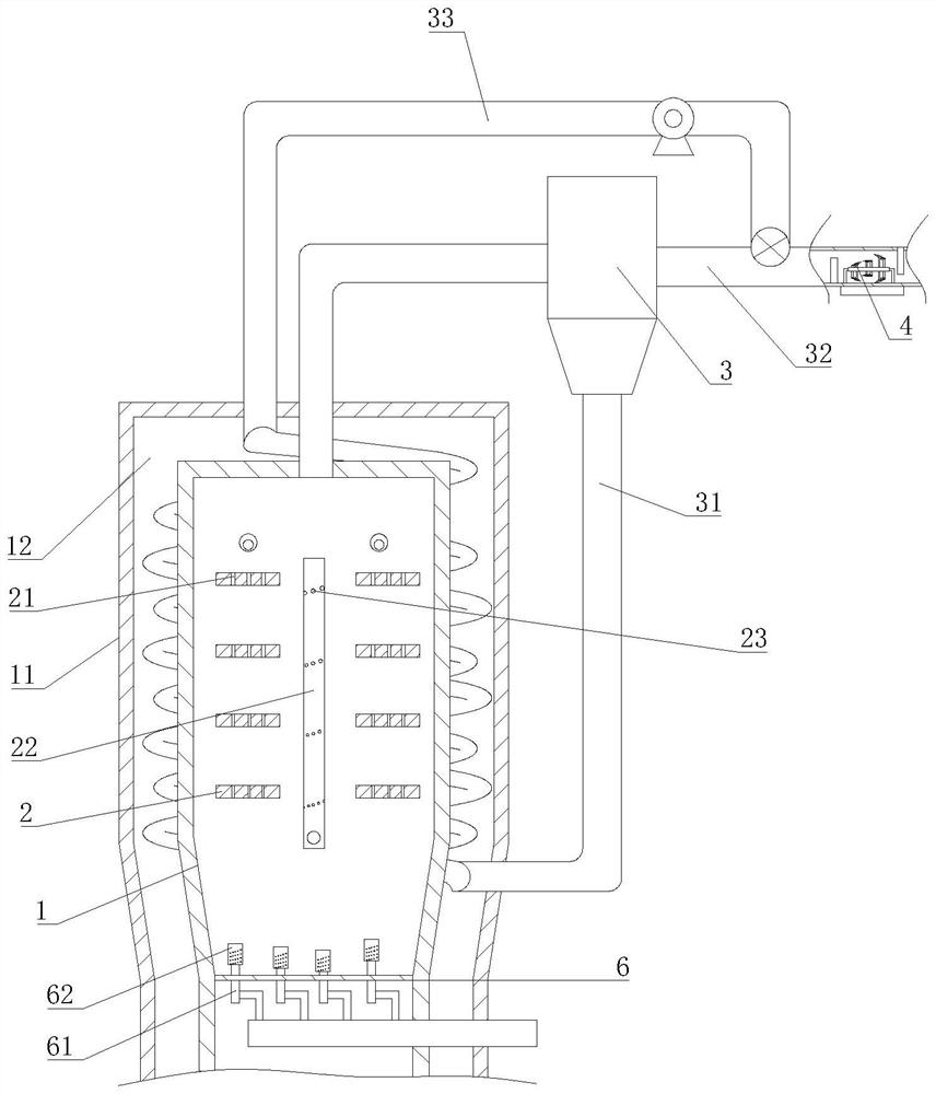
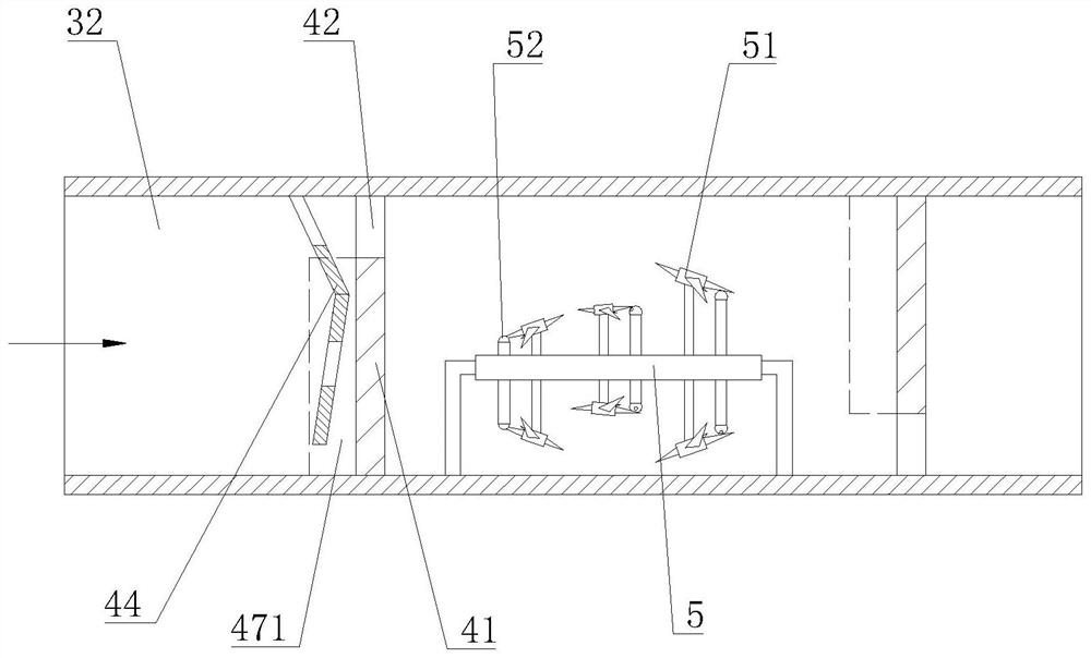
[0023] Such as Figure 1-7 As shown, an intelligent multi-level thermal power plant incineration flue gas circulation treatment system includes a boiler body 1, an insulation layer 11 is provided outside the boiler body 1, and an air layer 12 is formed between the insulation layer 11 and the boiler body 1; the boiler body 1 There are a number of burners 2 distributed in left and right rows from bottom to top, and a gas supply pipe 22 for supplementing fuel gas for each burner 2 is provided between the two rows of burners 2; the top of the boiler body 1 is connected to a separator through a smoke exhaust pipe 3. A fuel pipe 31 is connected to the discharge port of the separator 3. The fuel pipe 31 extends from the bottom of the boiler body 1 into the air layer 12 and spirals upward around the boiler body 1 to provide fuel for the uppermost burner 2; The exhaust port of the separator 3 is connected with a waste gas pipe 32, and the waste gas pipe 32 is provided with a circulatio...


PUM


Abstract

The intelligent multi-level thermal power plant incineration flue gas circulation treatment system comprises a boiler body, a heat preservation layer is arranged outside the boiler body, and an air layer is formed between the heat preservation layer and the boiler body; a plurality of combustors which are distributed in a left row and a right row are arranged in the boiler body from bottom to top, and a gas filling pipe for supplementing gas for each combustor is arranged between the two rows of combustors; the top of the boiler body is connected with a separator through a smoke exhaust pipe, a discharge port of the separator is connected with a fuel pipe, and the fuel pipe extends into the air layer from the lower portion of the boiler body and spirally extends upwards around the boiler body to provide fuel for the burner on the uppermost layer. An exhaust port of the separator is connected with a waste gas pipe, a circulating pipe is arranged on the waste gas pipe, and the circulating pipe extends into the air layer from the upper portion of the boiler body and spirally extends downwards around the boiler body to be connected with a gas filling pipe. The invention has the characteristics of sufficient combustion, energy saving and environmental protection.

Description

technical field [0001] The invention relates to a flue gas treatment system, in particular to an intelligent multi-level thermal power plant incineration flue gas circulation treatment system. Background technique [0002] The main working principle of the boiler is to use the heat energy released after fuel combustion or the waste heat in industrial production to transfer to the water in the container, so that the water reaches the required temperature or steam at a certain pressure. In the process of steam production, the state of boiler combustion has a very significant impact on steam generation, flue gas emission and fuel utilization. During the combustion process of the boiler, due to insufficient fuel combustion, the thermal decomposition temperature of nitrogen is lower than the combustion temperature of pulverized coal, so the nitrogen compounds in the fuel will be oxidized to form nitrogen oxides and nitrogen dioxide during combustion, and because coal will have C...

Claims


Application Information

Patent Timeline
Patent Type & Authority Applications(China)
IPC IPC(8): F23J15/02F23J15/06F23G5/44F23G5/46F23G5/50
CPCY02E20/30
Inventor 金国桦
Owner 湖州南太湖热电有限公司
Learn More