Simple channel device achieving spontaneous lighting
A kind of equipment and simple technology, applied in mechanical equipment, engine components, machines/engines, etc., can solve the problem of not having the advantage of water absorption
- Summary
- Abstract
- Description
- Claims
- Application Information
AI Technical Summary
Problems solved by technology
Method used
Image
Examples
Embodiment Construction
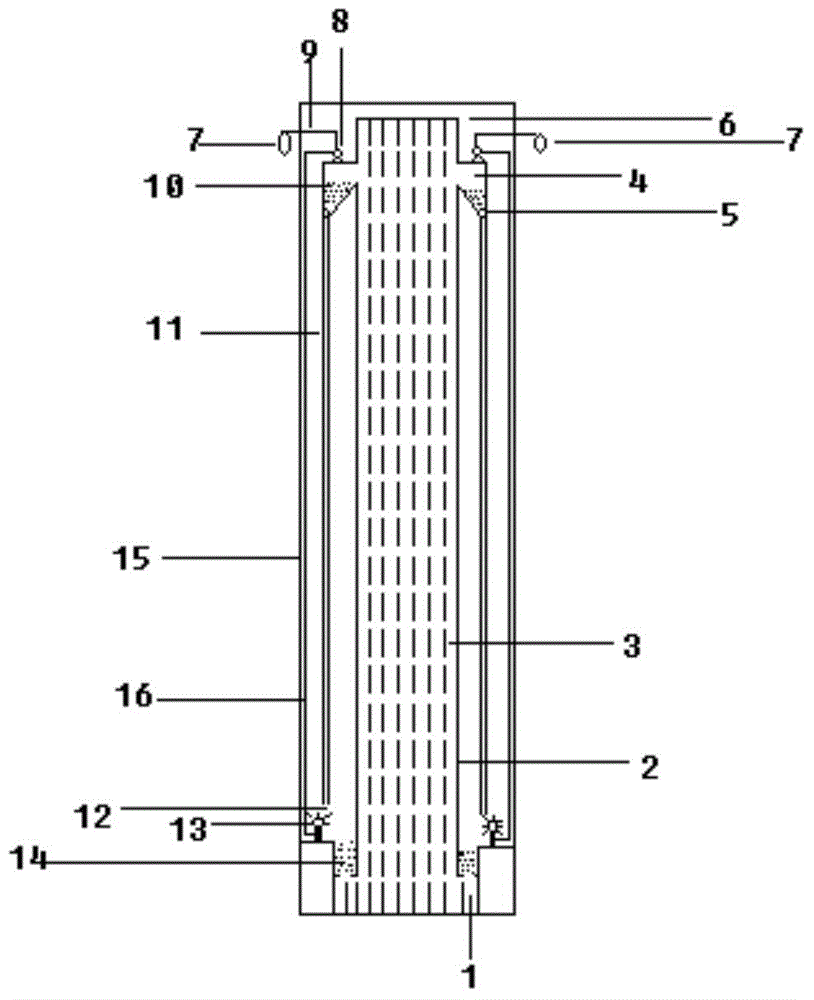
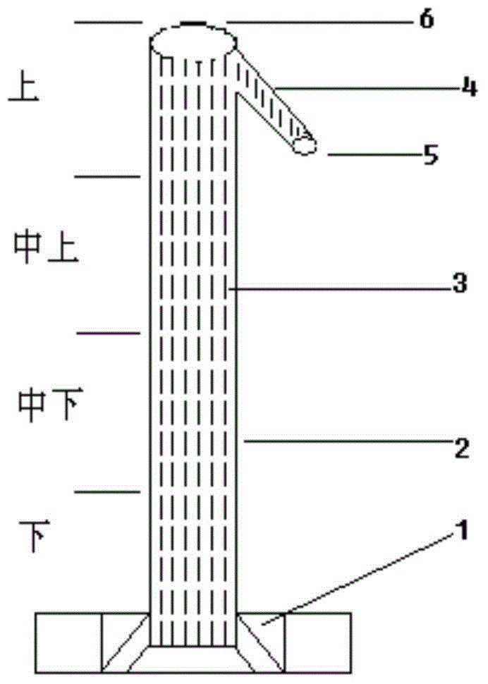
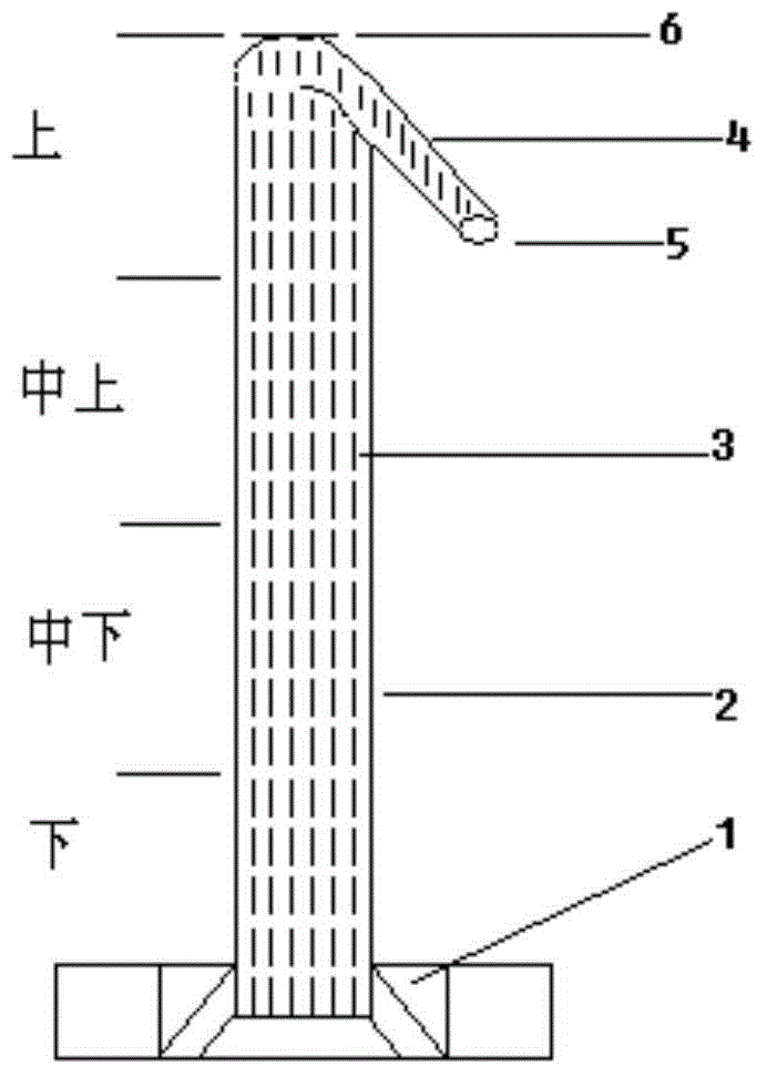
[0063] to attach figure 1 , attached figure 2 , attached image 3 As an example to explain the specific operation steps:
[0064] figure 2 and image 3 Yes figure 1 A separate schematic diagram of the "water flow up" functional module in . and figure 1 The difference of relevant functional modules is only the shape difference of structural parts, such as the position and shape of the pipe outlet body (4), and its basic structure is the same as that of figure 1 There is no difference in the structure of the "water upflow function module" expressed in , so the following only uses figure 1 structure to illustrate.
[0065] figure 1 It is a schematic diagram of spontaneous lighting equipment, which contains the structure of "water flowing up" equipment inside. In the "water flowing up" equipment, 1 is the submerged body, 2 is the outer casing of the pipe, 3 is the capillary pipe inside the pipe, and 4 is the outlet of the pipe. Water body, 5 is the water outlet, 6 is t...
PUM
 Abstract
Description
Claims
Application Information
 - R&D
- Intellectual Property
- Life Sciences
- Materials
- Tech Scout
- Unparalleled Data Quality
- Higher Quality Content
- 60% Fewer Hallucinations
Browse by: Latest US Patents, China's latest patents, Technical Efficacy Thesaurus, Application Domain, Technology Topic, Popular Technical Reports.
© 2025 PatSnap. All rights reserved.Legal|Privacy policy|Modern Slavery Act Transparency Statement|Sitemap|About US| Contact US: help@patsnap.com


