Encoder connector

An encoder and coupling technology, applied in the direction of couplings, rigid shaft couplings, bearings, etc., can solve the problems of reduced life, unfavorable encoder mechanical structure, encoder damage, etc., to reduce the difficulty of installation and adjustment, improve Noise immunity, the effect of reducing measurement costs

Active Publication Date: 2016-03-02
WISDRI ENG & RES INC LTD
View PDF8 Cites 6 Cited by
  • Summary
  • Abstract
  • Description
  • Claims
  • Application Information

AI Technical Summary

Problems solved by technology

When the light-duty encoder is used in poor conditions, the life will be greatly reduced
The main reasons for this situation are: 1. The installation accuracy is not enough
The installation of the traditional rotary encoder is very simple. The encoder is directly installed on the small shaft, and the circular runout of the small shaft is required to be controlled within 0.05mm; as an assembly, the small shaft cannot be adjusted to meet the installation accuracy requirements in many occasions, so it is often possible during operation. It is seen that the encoder shakes slightly following the small shaft; this kind of shaking is not conducive to the mechanical structure inside the encoder; at the same time, occasionally the small shaft will move along with the rollers of the rotating equipment, and the impact caused by these movements will be transmitted to the encoder , directly reduce the life of the encoder
2. The encoder has withstood a certain impact
Encoders are mostly used in shaft-type rotating equipment. The output shaft of this type of equipment will have some movement more or less. This movement can bring a certain impact, which is very unfavorable to the encoder.
3. During the use of the encoder, foreign objects seep into it and cause damage
When the working environment of the encoder is affected by oil and water for a long time, if it is not protected, the oil and water will seep into the encoder and pollute the code disc, etc., thus damaging the encoder

Method used


Image

  • Encoder connector
  • Encoder connector
  • Encoder connector

Examples


Embodiment Construction

[0018] In order to make the object, technical solution and advantages of the present invention clearer, the present invention will be further described in detail below in conjunction with the accompanying drawings and embodiments. It should be understood that the specific embodiments described here are only used to explain the present invention, not to limit the present invention.

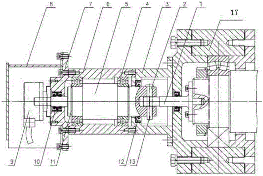
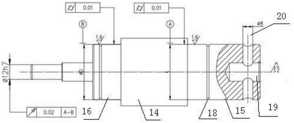
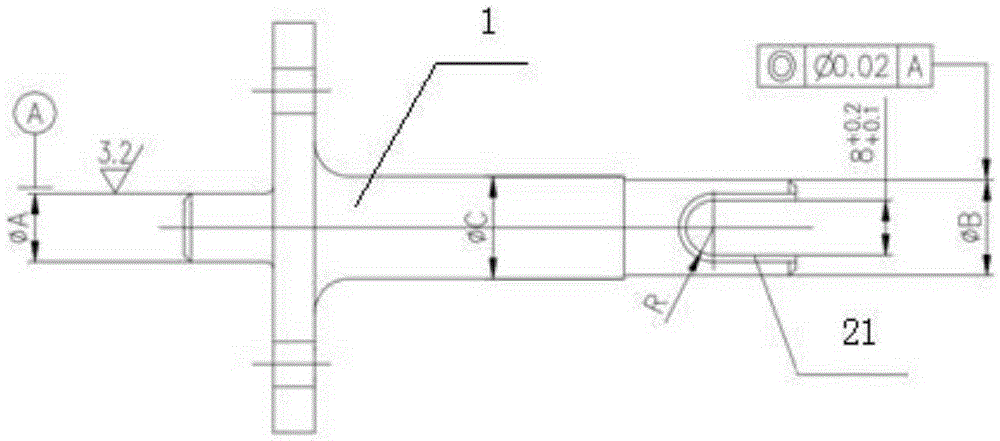
[0019] see Figure 1-Figure 3 , an encoder coupling, including a small shaft 1 installed at the end of a roller of a rotating device 17, and a large shaft 5 connected to an encoder 9;

[0020] The large shaft 5 is fixed in the bearing seat 6 through two bearings 4, and one of the bearings 4 is a fixed end (that is, the inner ring and the outer ring of the bearing are axially constrained so that they cannot move), and the bearing seat 6 One end is connected to the shell of the rotating device 17 through the inner end cover 3, the other end of the bearing housing 6 is connected to the outer end cove...


PUM


Abstract

The invention discloses an encoder connector. The encoder connector comprises a small shaft connected with a roller of rotary equipment and a large shaft connected with an encoder, wherein the large shaft is connected with a bearing block through two bearings, one end of the bearing block is connected with a casing of the rotary equipment through an inner end cover, the other end of the bearing block is connected with an outer end cover, a protection cover is arranged outside the outer end cover, and the encoder is arranged in the protection cover; a first sealing unit is arranged between the large shaft and the inner end cover, and a second sealing unit is arranged between the large shaft and the outer end cover; a U-shaped groove is formed in a connection shaft of the small shaft; the connection shaft with the U-shaped groove is fixed by a straight pin after being inserted in a connection hole in the front end of the large shaft. The encoder is directly installed on the encoder connector, and impact, oil and water permeation and the like are isolated to a certain extent by the aid of the encoder connector, so that the service life of the encoder is prolonged.

Description

technical field [0001] The invention relates to an encoder connection device, in particular to an encoder coupling. Background technique [0002] Rotary encoders are widely used in industry. According to the strength of anti-interference, they can be divided into heavy-duty type and light-duty type. The price difference between the two types of encoders is large, so light-duty type encoders are still mostly used in applications. When the light-duty encoder is used in poor conditions, the life will be greatly reduced. The main reasons for this situation are: 1. The installation accuracy is not enough. The installation of the traditional rotary encoder is very simple. The encoder is directly installed on the small shaft, and the circular runout of the small shaft is required to be controlled within 0.05mm; as an assembly, the small shaft cannot be adjusted to meet the installation accuracy requirements in many occasions, so it is often possible during operation. It is seen t...

Claims


Application Information

Patent Timeline
Patent Type & Authority Applications(China)
IPC IPC(8): F16C35/12F16D1/02F16J15/06
CPCF16C35/12F16C2300/00F16D1/02F16J15/06
Inventor 卓松生陈海清
Owner WISDRI ENG & RES INC LTD
Why Eureka
Try Eureka