Method for combined navigation of inertia/visual odometer/laser radar

A visual odometer and laser radar technology, applied in the field of navigation, can solve problems such as large amount of calculation, unusability, and impact on the accuracy of results, and achieve the effect of high-precision navigation

Active Publication Date: 2016-03-02
BEIJING AUTOMATION CONTROL EQUIP INST
View PDF6 Cites 44 Cited by
  • Summary
  • Abstract
  • Description
  • Claims
  • Application Information

AI Technical Summary

Problems solved by technology

However, there are many combinations of information that can be selected. If all these information are combined, although the accuracy can meet or even exceed the requirements, the calculation amount is huge and cannot be used in practice. The sequence and the specific combination will have a huge impact on the accuracy of the results
In the prior art, there is no perfect combination method, which can not only take into account the amount of calculation, but also minimize the content of the combination

Method used


Image

  • Method for combined navigation of inertia/visual odometer/laser radar
  • Method for combined navigation of inertia/visual odometer/laser radar
  • Method for combined navigation of inertia/visual odometer/laser radar

Examples


Embodiment Construction

[0055] A combined navigation method of inertial / visual odometer / lidar, comprising the steps of:

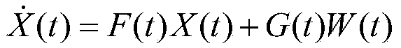
[0056] (1) The establishment of the state model of the inertial / visual odometer / lidar integrated navigation system is as follows

[0057] X · ( t ) = F ( t ) X ( t ) + G ( t ) W ( t )

[0058] In the formula: X(t) is the state vector of the above system; W(t) is the white noise of the system; the coefficient matrices F(t) and G(t) are obtained according to the error equation.

[0059] X(t)=[δV n ,δV u ,δV e ,δL,δh,δλ,φ n ,φ u ,φ e ,▽ x ,▽ y ,▽ z ,ε x ,ε y ,ε z ,δV n_ov ,δV e_OV ]

[0060] δV n ,δV u ,δV e Respectively represent ...


PUM


Abstract

The invention belongs to navigation methods and particularly relates to a method for combined navigation of an inertia/visual odometer/laser radar. The method comprises (1) state model establishment, (2) visual odometer speed measurement based on characteristic information, (3) establishment of a measurement equation and obtaining of a measurement value, (4) Kalman filtering and (5) system error correction. The method has the advantages that a machine vision autonomous navigation technology is used, a monocular camera can measure a vector speed under the conditions of a known distance through the difference of a front frame image and a rear frame image, the laser radar can accurately measure the distance of an observation point and then measure a vector speed, navigation is performed by utilizing combination of the speed obtained through measurement and an inertial reference speed, and high-accuracy navigation is performed finally under the conditions of no outside reference information.

Description

technical field [0001] The invention belongs to a navigation method, in particular to an inertial / visual odometer / laser radar combined navigation method. Background technique [0002] As the capability of long-term and long-distance navigation of aircraft continues to increase, the requirements for the accuracy and autonomy of the navigation system are also increasing. The pure inertial navigation system cannot fully meet the needs of practical applications due to its inherent disadvantage that navigation errors accumulate over time. There are two ways to solve this problem: first, improve the precision of the inertial navigation system itself. Mainly rely on the adoption of new materials, new processes, and new technologies to improve the precision of inertial devices, or to develop new high-precision inertial devices. But it needs to spend a lot of human and financial resources, and the improvement of the precision of inertial devices is limited. Second, adopt integrate...

Claims


Application Information

Patent Timeline
Patent Type & Authority Applications(China)
IPC IPC(8): G01C21/00G01C21/16G01S17/02G01S17/58
CPCG01C21/005G01C21/165G01S17/58G01S17/86
Inventor 孙伟李海军郭元江徐海刚李群郑辛张忆欣刘冲裴玉锋原润
Owner BEIJING AUTOMATION CONTROL EQUIP INST
Why Eureka
Try Eureka