Gain measuring device and method of cascaded micro channel plate

A technology of microchannel plate, measuring method, applied in the direction of measuring device, measuring electricity, measuring electric variable, etc.

Active Publication Date: 2016-03-02
NORTH NIGHT VISION TECH
View PDF9 Cites 9 Cited by
  • Summary
  • Abstract
  • Description
  • Claims
  • Application Information

AI Technical Summary

Problems solved by technology

The method for measuring the gain of the cascaded microchannel plate measures the input current of the weak cascaded microchannel plate by measuring the number of bright spots on the fluorescent screen, and measures

Method used


Image

  • Gain measuring device and method of cascaded micro channel plate
  • Gain measuring device and method of cascaded micro channel plate
  • Gain measuring device and method of cascaded micro channel plate

Examples


Embodiment 1

[0064] Gain of two cascaded MCPs

[0065] The measurement is carried out in a dark room at a temperature of 21-25°C. The measured cascaded MCP has an effective working diameter of Φ18mm, an outer diameter of Φ25mm, and a channel diameter of Φ6μm, which are MCPs used in conventional image intensifiers.

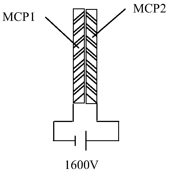
[0066] Put the output end of the first MCP and the input end of the second MCP close together, then put it into a special measurement fixture and put it into the MCP gain measurement device. The fixture used is a common MCP measurement fixture.

[0067] Close the baffle, insert the UV neutral density filter, start the vacuum system of the equipment, and start vacuuming. When the vacuum degree of the measurement system reaches 5×10 -5 After lifting, turn on the high-voltage power supply and apply the required working voltage to the measured MCP, photocathode and fluorescent screen; the input voltage of the first MCP is -1600V, the output voltage of the second MCP is zero potenti...

Embodiment 2

[0080] Gain of three cascaded MCPs

[0081] The measurement is carried out in a dark room at a temperature of 21-25°C. The measured MCP has an effective working diameter of Φ18mm, an outer diameter of Φ25mm, and a channel diameter of Φ6μm, which is the MCP used in conventional image intensifiers.

[0082] Put the output end of the first MCP close to the input end of the second MCP, then put the output end of the second MCP close to the input end of the third MCP, then put it into the special measuring fixture and place it into the MCP gain measurement device. The fixture used is a common MCP measuring fixture.

[0083] Close the baffle, insert the UV neutral density filter, start the vacuum system of the equipment, and start vacuuming. When the vacuum degree of the measurement system reaches 5×10 -5 After Torr, turn on the high-voltage power supply, and apply the required operating voltage to the three cascaded MCPs, photocathode and phosphor screen to be measured. The inp...


PUM


Abstract

The invention discloses a gain measuring device and method of a cascaded micro channel plate (MCP). The method comprises the following steps that: step (1) after being attenuated, ultraviolet light is emitted to a quartz window, and an ultraviolet Au photocathode is excited to emit photoelectrons; step (2) under the action of electric fields, the photoelectrons are emitted to the input end of the cascaded MCP, and are multiplied by the cascaded MCP, and the multiplied photoelectrons are outputted from the output end of the cascaded MCP, and the multiplied photoelectrons bombard a fluorescent screen under the action of the electric fields, so that bright spots can be generated; step (3) the bright spots on the fluorescent screen are imaged by a CCD or CMOS camera, and a computer acquires the output signals of the CCD or CMOS camera so as to measure the number of the bright spots; and (4) after the number of the bright spots is measured, a circuit is switched to the output current loop of the cascaded MCP, and a nanoammeter is connected in series in the loop so as to measure the output current of the cascaded micro channel plate (MCP), and the gain of the cascaded micro channel plate (MCP) is calculated according to the number of the bright spots and the output current of the cascaded micro channel plate (MCP). The gain measuring method of the cascaded micro channel plate (MCP) provided by the invention has the advantages of simple operation and high accuracy.

Description

technical field [0001] The invention belongs to the technical field of microchannel plates (MCP), in particular to a gain measurement device and method of cascaded microchannel plates. Background technique [0002] A microchannel plate (MCP) is a two-dimensional electron multiplier with a large array of microwells, and its microwell size is usually about Φ4 μm to 10 μm. An MCP with an effective diameter of Φ18mm has about one million channels. A semiconductor material that can emit secondary electrons is coated on the inner wall of each channel of the MCP. When a certain voltage is applied to the input and output terminals of the MCP, a uniform electric field will be generated in each channel. . This electric field is axial, which can make the electrons entering the channel collide with the MCP channel wall to generate secondary electrons (or secondary electrons), and the secondary electrons are accelerated under the action of the axial electric field, and the secondary el...

Claims


Application Information

Patent Timeline
IPC IPC(8): G01R31/25
CPCG01R31/252
Inventor 李晓峰李金沙苏德坦李靖文褚祝军郭骞姜云龙姬明李永春
Owner NORTH NIGHT VISION TECH
Why Eureka
Try Eureka