
Apparatus for improving optical fiber output laser light spot homogenization

A laser and light spot technology, applied in the field of optoelectronics, can solve the problems of complex device, burnt fiber, troublesome installation, etc., and achieve the effect of improving light spot, high safety and simple structure

Inactive Publication Date: 2016-03-02
Shandong Huaguang Optoelectronics Co. Ltd.
View PDF8 Cites 4 Cited by
  • Summary
  • Abstract
  • Description
  • Claims
  • Application Information

AI Technical Summary

Problems solved by technology

However, the patent applies stress to the optical fiber, which is easy to cause damage to the optical fiber. If the laser works for a long time, the optical fiber will be burned out, causing unnecessary losses.
[0006] Chinese patent document CN10336495556A discloses a method of applying stress to the optical fiber to improve the spatial distribution of the output laser beam of the optical fiber, and at the same time, the slight vibration brought by the vibration motor to the optical fiber homogenizes the interference speckle on the irradiation surface. This patent requires the application of a vibration motor, and the device is complicated. , installation trouble

Method used


Image

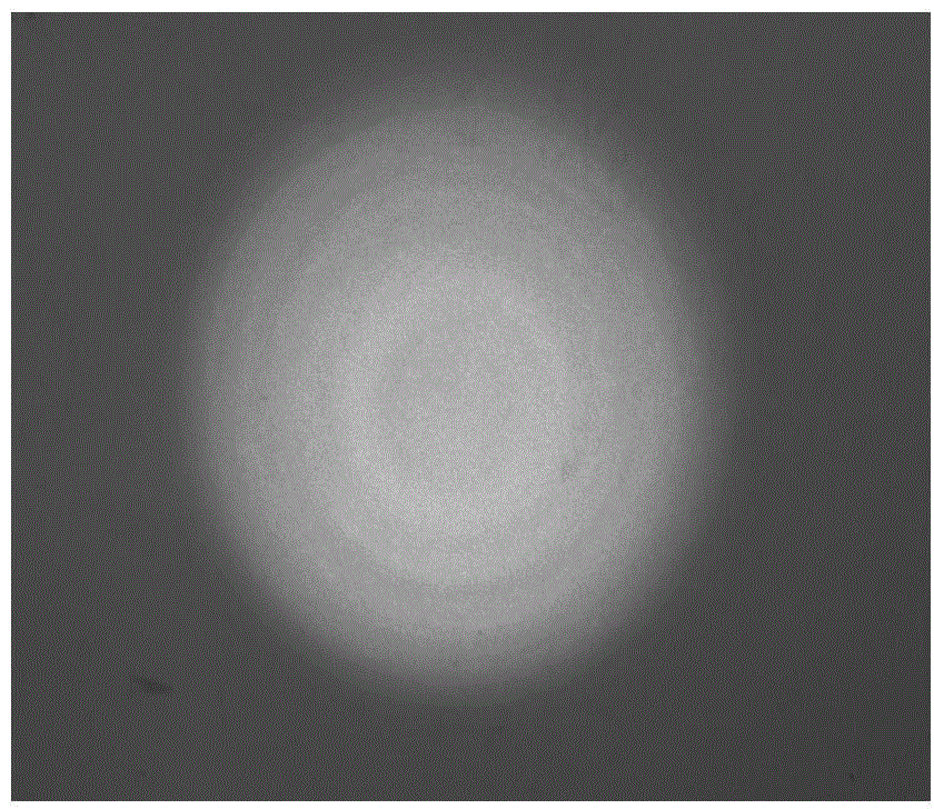
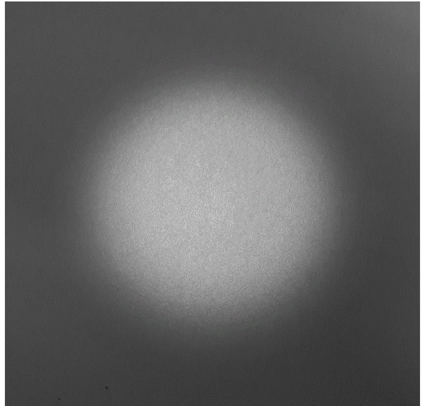
  • Apparatus for improving optical fiber output laser light spot homogenization
  • Apparatus for improving optical fiber output laser light spot homogenization
  • Apparatus for improving optical fiber output laser light spot homogenization

Examples


Embodiment 1

[0029] Such as Figure 1-3 shown.

[0030] A device for improving the uniformity of the light spot of a fiber output laser, comprising a fiber protection tube 2 and a bend tube 3 sheathed outside the fiber protection tube 2 .

[0031] The curved tube includes a single arc tube or a plurality of arc tubes. The core diameter of the optical fiber is 400 μm, and the included angle between tangent lines tangent to both ends of the arc tube is 135°.

Embodiment 2

[0033] Such as Figure 6 shown.

[0034] According to the device for improving spot homogenization of a fiber output laser according to Embodiment 1, the difference lies in that the bent pipe is a single corrugated pipe or a plurality of corrugated pipes.

Embodiment 3

[0036] Such as Figure 7 shown.

[0037] According to the device for improving spot homogenization of a fiber output laser according to Embodiment 2, the difference is that the bent pipe is a single S-shaped pipe or multiple S-shaped pipes.


PUM


Abstract

The invention relates to an apparatus for improving optical fiber output laser light spot homogenization. The apparatus comprises an optical fiber, an optical fiber protection pipe and a bended pipe. According to different light spot output requirements, different bended pipes are installed; the bended pipe is installed on the optical fiber or the optical fiber protection pipe to change light phase propagation mode distribution in a multimode fiber. Therefore, spatial distribution of light beams outputted from an optical fiber end surface is changed and a purpose of improving optical spots is reached.

Description

technical field [0001] The invention relates to a device for improving the homogenization of light spots of an optical fiber output laser, belonging to the technical field of optoelectronics. Background technique [0002] Since Corning Corporation of the United States successfully developed the world's first practical silica optical fiber in the early 1970s, the optical fiber communication using optical fiber as the transmission medium and the derived optical fiber sensor technology have developed rapidly. In the optical path structure using optical fiber to transmit light beam, semiconductor laser (LD) is often used as light source, and coupling technology is used to realize the connection between optical fiber and optical receiver. Therefore, the coupling efficiency directly affects the performance of optical fiber communication system. The coupling system of semiconductor laser and optical fiber can be summarized into two categories: the coupling system composed of discre...

Claims


Application Information

Patent Timeline
Patent Type & Authority Applications(China)
IPC IPC(8): G02B27/09G02B27/48
Inventor 邵慧慧于果蕾刘成成苏建李沛旭徐现刚
Owner Shandong Huaguang Optoelectronics Co. Ltd.
Learn More