Three-phase phase-change switch device

A commutation switch, three-phase technology, applied in the direction of reducing the asymmetry of the multi-phase network, eliminating/reducing the asymmetry of the multi-phase network, etc., which can solve the problems of switching the power supply phase and power failure

Inactive Publication Date: 2016-03-02
STATE GRID GANSU ELECTRIC POWER CORP +2
View PDF5 Cites 20 Cited by
  • Summary
  • Abstract
  • Description
  • Claims
  • Application Information

AI Technical Summary

Problems solved by technology

[0004] The problem to be solved by the present invention is to provide a three-phase commutation switch device to solve the related p

Method used


Image

  • Three-phase phase-change switch device
  • Three-phase phase-change switch device
  • Three-phase phase-change switch device

Examples


Embodiment 1

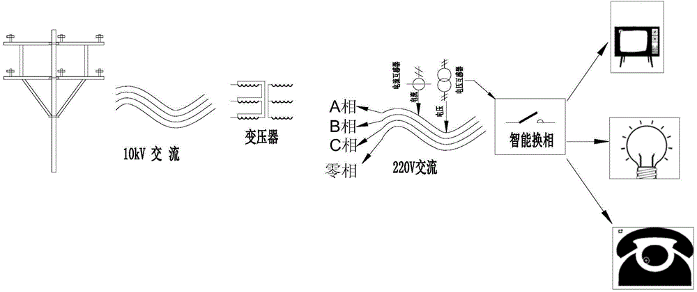
[0056] image 3 It is a system structure diagram of the three-phase reversing switch device of the present invention. Please combine figure 1 Each phase of the three-phase alternating current at the outlet of the distribution transformer is connected to a voltage transformer and a current transformer to measure the three-phase voltage. All collected and measured data can be calculated based on three-phase voltage, current, phase sequence, etc. The voltage transformer and the current transformer respectively output a milliampere level tiny current signal at the output end.

[0057]The output terminals of the voltage transformer and current transformer are connected to the AD conversion circuit. The core of the AD conversion circuit is a 16-bit high-precision AD acquisition chip for multi-channel acquisition. The three-phase voltage and current are connected to the analog input port of the AD acquisition chip. Within a certain period of time, the voltage and current of each p...

Embodiment 2

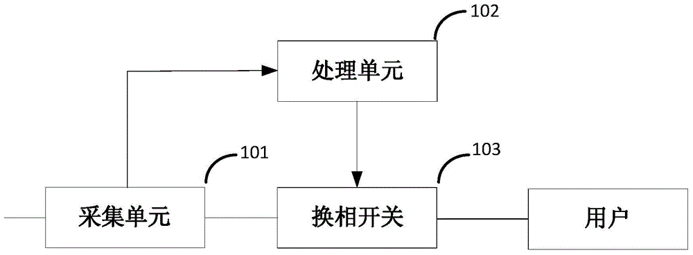
[0078] See Figure 5 , as shown in the figure is a schematic diagram of a control system composed of multiple three-phase commutation switches, compared to figure 1 , the principle of embodiment 2 is the same as that of embodiment 1, and there is no substantial difference.

[0079] Specifically, after the acquisition unit 101 completes a period of data acquisition of the three-phase alternating current in the power distribution line, the data is converted into a digital signal through an AD conversion circuit, and the three-phase voltage and current is calculated in the processing unit 102 (CPU). Value, active power, reactive power, voltage and current phase sequence, power factor and other parameters. These data are sent to the remote server 104 through the processing unit 102 . Wherein, the processing unit 102 may choose to use wired communication, or use other short-distance wireless communication methods such as GPRS to perform data communication with the remote server 1...


PUM


Abstract

The invention provides a three-phase phase-change switch device. The three-phase phase-change switch device comprises an acquisition unit electrically connected with a transmission line at the outlet of a distribution transformer and used for acquiring the voltage data and the current data of an AC in the transmission line; a processing unit electrically connected with the acquisition unit and used for analyzing the voltage and current data of the acquisition unit, determining whether the voltage and current data reach a threshold value condition, and deciding whether to switch a phase-change switch and send out a phase-change instruction; the phase-change switch electrically connected with the transmission line at a load concentration position and used for receiving the phase-change instruction to switch the phase of the AC in the transmission line. The three-phase phase-change switch device of the invention can monitor the three-phase AC automatically, acquire the phase sequence of each phase of voltage and current real-timely and report to a background regularly. When the three-phase power supply loads are unbalanced, the three-phase phase-change switch device can switch the phases automatically according to a set value, or report to the background immediately and actively and execute a switching command of the background, thereby carrying out the on-site or remote phase switching on the AC.

Description

technical field [0001] The invention relates to the field of power transmission, in particular to a three-phase commutation switch device. Background technique [0002] The total capacity of transformers currently in operation in my country is about 3.5×10 9 kVA, because the total number of transformers is large and the capacity is large, the power loss is huge. According to statistics, the power loss of distribution transformers (hereinafter referred to as distribution transformers) alone is about 30-50 TWh per year, accounting for about 2-3% of the total power generation. At present, the capacity of low-efficiency distribution transformers operating on the power grid for more than 20 years is about 2.4×10 8 kVA, due to the aging of these distribution transformer parameters, high loss, many defects, and poor operational reliability, it threatens the safe operation of the power grid. Therefore, the transformation task of distribution transformer and the potential for ener...

Claims


Application Information

Patent Timeline
IPC IPC(8): H02J3/26
CPCY02E40/50
Inventor 杨青峰刘克发王飞行向驰魏立保王彦彪柳占杰于伟赵海明王宁
Owner STATE GRID GANSU ELECTRIC POWER CORP
Why Eureka
Try Eureka