Rotor for a gantry of a computed tomograpy apparatus

A technology of tomography and computer, which is applied in the direction of radiation diagnosis equipment, computer tomography scanner, diagnosis, etc. It can solve the problems of image quality damage and achieve the effect of reducing material input, weight reduction and failure rate

Inactive Publication Date: 2016-03-09
SIEMENS AG
View PDF7 Cites 3 Cited by
  • Summary
  • Abstract
  • Description
  • Claims
  • Application Information

AI Technical Summary

Problems solved by technology

[0006] The combination of high rotational speed, large rotational radius and high rotational mass makes the rotor a mechanically highly loaded component which, in addition to absorbing the stresses that occur, must also ensure the maintenance of the X-ray tube and detector in position, because of the A position shift of more than 0.15mm can cause serious damage to image quality

Method used


Image

  • Rotor for a gantry of a computed tomograpy apparatus
  • Rotor for a gantry of a computed tomograpy apparatus
  • Rotor for a gantry of a computed tomograpy apparatus

Examples


Embodiment Construction

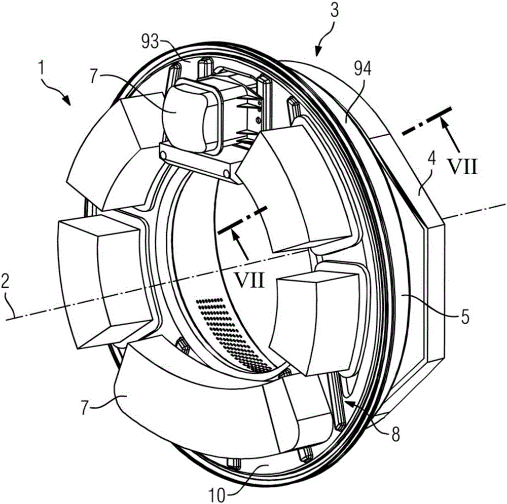
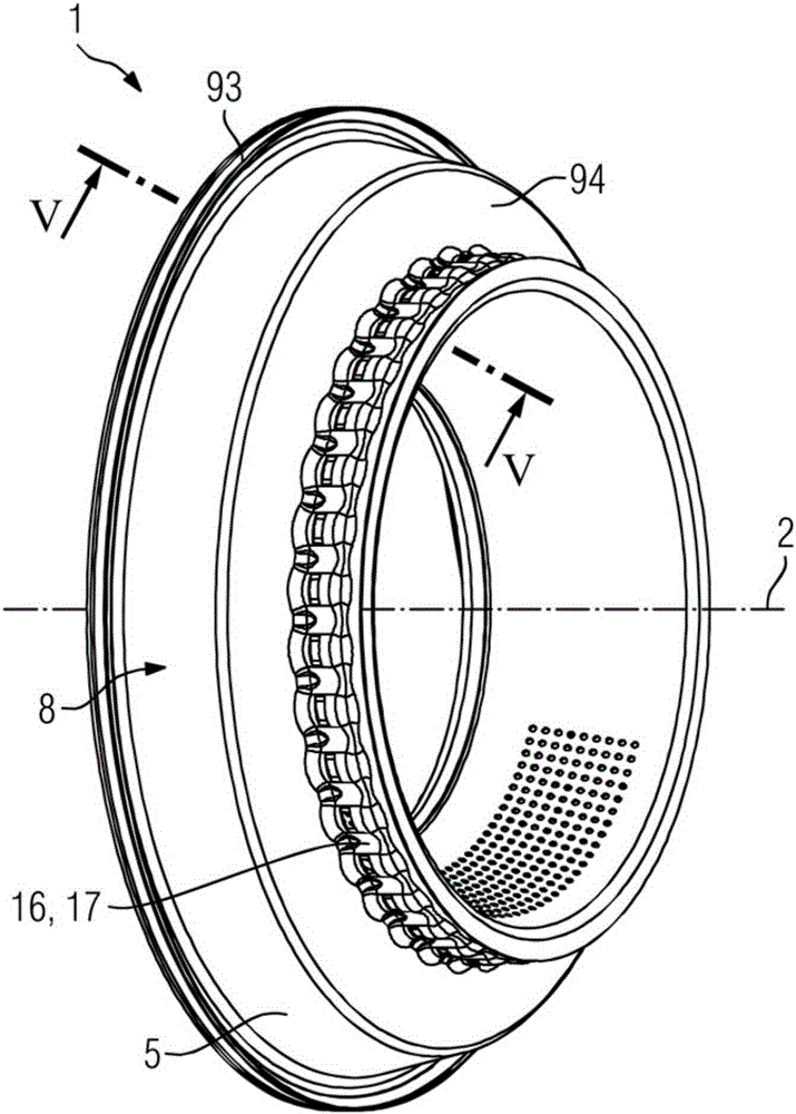
[0033] exist figure 1 3 shows in perspective a part of a gantry 3 of a computed tomography system 27 , wherein the gantry 3 comprises a stationary rotating frame 4 and a rotor 1 according to the invention arranged rotatably via a rotary bearing arrangement 6 . The rotor 1 is designed at least in one section as a hollow body 8 , wherein the hollow body 8 has a hollow profile cross section in at least one half-plane defined by the axis of rotation 2 of the rotor 1 . An example of a half-plane defined by the axis of rotation 2 of the rotor 1 is the figure 1 The axis of rotation 2 of the middle rotor 1 delimits and includes the half-plane of the section line VII-VII.

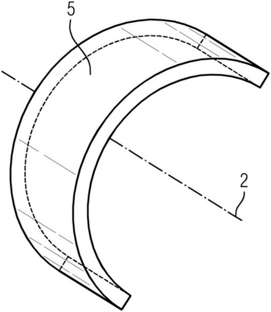
[0034] The hollow body 8 is preferably designed as a supporting structure, which is suitable for holding the component 7 of the recording device of the computed tomography system 27 . The rotor 1 preferably has at least one flat part 5 , wherein the at least one flat part 5 forms a section of the hollow body 8 at ...


PUM


Abstract

A rotor (1) for a gantry (3) of a computed tomography device (27) is formed as a hollow body (8) at least in one section. The hollow body (8) has a hollow profile cross-section in at least one half-plane defined by the axis (2) of rotation of the rotor (1).

Description

technical field [0001] The invention relates to a rotor for a gantry of a computed tomography system. Background technique [0002] Computed tomography devices enable the reconstruction of three-dimensional slice or volume images of an examination region for diagnostic purposes. The reconstruction of the image is based on projections obtained from different projection directions from the examination region by rotation of the recording device, so that for the reconstruction of the image there is a possibility for parallel projections obtained from an angular range of at least 180 degrees plus the fan angle. Measurement data. To enable the rotation of the imaging device, the computed tomography system has a gantry comprising a stationary rotating frame and a rotor arranged rotatably by means of a rotary bearing arrangement, on which the imaging device is held. [0003] The task of the gantry of the computed tomography system is in particular to guide the components of the im...

Claims


Application Information

Patent Timeline
Patent Type & Authority Applications(China)
IPC IPC(8): A61B6/03
CPCA61B6/035A61B6/4435
Inventor A.詹希
Owner SIEMENS AG
Why Eureka
Try Eureka