Direct-drive type ball grinding mill system for low-speed large-torque permanent magnet motor

A permanent magnet motor, high torque technology, applied in grain processing and other directions, to avoid loosening, good sealing and compact structure

Active Publication Date: 2016-03-09
HEBEI NEWSTAR ELECTRIC MOTOR CO LTD
View PDF6 Cites 7 Cited by
  • Summary
  • Abstract
  • Description
  • Claims
  • Application Information

AI Technical Summary

Problems solved by technology

[0005] The object of the present invention is to provide a low-speed high-torque permanent magnet motor direct-drive ball mil

Method used


Image

  • Direct-drive type ball grinding mill system for low-speed large-torque permanent magnet motor
  • Direct-drive type ball grinding mill system for low-speed large-torque permanent magnet motor
  • Direct-drive type ball grinding mill system for low-speed large-torque permanent magnet motor

Examples


Example Embodiment

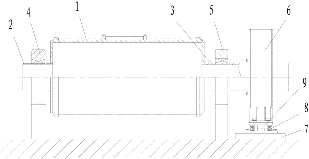
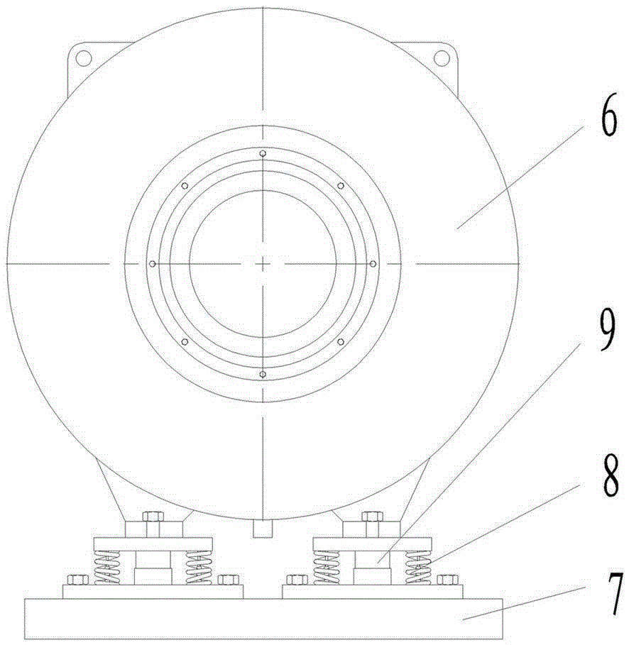
[0028] Example 1: See attached Figure 1-3 , The present invention provides a low-speed high-torque permanent magnet motor direct-drive ball mill system, which includes a barrel 1, a first support shaft 2 and a second support shaft 3 arranged at both ends of the barrel 1, respectively and the first support shaft 2 and the second supporting shaft 3 installed the first bearing housing 4 and the second bearing housing 5 and the permanent magnet motor 6 directly connected to the second supporting shaft 3, the key lies in: the bottom of the permanent magnet motor 6 is equipped with self-adaptability Flexible positioning device. The adaptive flexible positioning device includes a support base 7 and a buffer spring 8 and a damper device arranged between the support base 7 and the permanent magnet motor 6. The buffer springs 8 are provided in multiple and divided into two groups It is symmetrically arranged on both sides of the damper device.

[0029] In this embodiment, the damping devi...

Example Embodiment

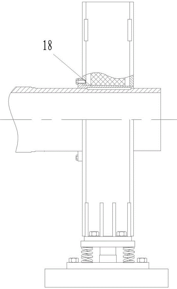
[0038] Example 2: See attached Figure 8 The difference from the first embodiment is that the first supporting shaft 2 is also an elongated structure and is directly connected to the permanent magnet motor 6, and the bottom of the permanent magnet motor 6 is also provided with an adaptive flexible positioning device. The driving of the two permanent magnet motors 6 makes the rotation process of the cylinder 1 more balanced.

Example Embodiment

[0039] Example 3: See attached Picture 9 The difference from the first and second embodiments is that the permanent magnet motor 6 is directly connected to the cylinder 1, and the bottom of the permanent magnet motor 6 is provided with an adaptive flexible positioning device.


PUM


Abstract

The invention discloses a direct-drive type ball grinding mill system for a low-speed large-torque permanent magnet motor and relates to the technical field of ball grinding mill equipment. The direct-drive type ball grinding mill system comprises a cylinder body, a first supporting rotating shaft, a second supporting rotating shaft, a first bearing block, a second bearing block and the permanent magnet motor, wherein the first supporting rotating shaft and the second supporting rotating shaft are arranged at the two ends of the cylinder body, the first bearing block and the second bearing block are installed with the first supporting rotating shaft and the second supporting rotating shaft respectively, and the permanent motor is directly connected with the cylinder body and/or the supporting rotating shafts. The direct-drive type ball grinding mill system is characterized in that a self-adaptation flexible positioning device is arranged at the bottom of the permanent magnet motor and comprises a supporting base, buffering springs and a damping device, wherein the buffering springs and the damping device are arranged between the supporting base and the permanent magnet motor; and the buffering springs are symmetrically arranged on the two sides of the damping deice. The direct-drive type ball grinding mill system has the beneficial effects that the upper end of the damping device abuts against the bottom of a shell of the motor and is not connected with the shell of the motor, the buffering springs are connected with the supporting base and the shell of the motor respectively, the motor can be adaptive to the coaxiality error of a ball grinding mill through the self-adaption flexible positioning device, vibration in various directions is buffered, and the motor is protected.

Description

Technical field [0001] The invention relates to the field of ball mill products, in particular to an improved low-speed high-torque permanent magnet motor direct-drive ball mill system. Background technique [0002] The ball mill is the key equipment for fine grinding of materials. It is widely used in industries that need to pulverize raw materials such as mineral processing, building materials, and chemical industries. It is a high-fine grinding machine widely used in industrial production. The ball mill includes a horizontal cylinder, a hollow shaft for feeding and discharging materials, and a grinding head. The cylinder is a long cylinder with spherical abrasives inside. The barrel is made of steel plate, and the inner wall is fixed with steel wear-resistant liner. The grinding body is generally a steel ball, and is filled into the barrel according to different diameters and a certain proportion. After mixing with the material, the roller rotates at a low speed to form rollin...

Claims


Application Information

Patent Timeline
IPC IPC(8): B02C17/18B02C17/24
CPCB02C17/18B02C17/24
Inventor 牛英力李建军赵小云李旭东
Owner HEBEI NEWSTAR ELECTRIC MOTOR CO LTD
Why Eureka
Try Eureka